– 9 –
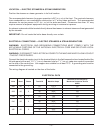
LOCATION — ELECTRIC STEAMERS & STEAM GENERATORS
Position the steamer or steam generator in its final location.
The recommended clearance for proper operation is 36" (
91.4 cm) at the front. The required clearance
from combustible or non-combustible construction is 0" at the sides and back. The recommended
clearance for service access is 18" (
45.7 cm) at the sides and back. Clearances less than 18" may
require removal of adjacent equipment during servicing at customer's expense.
An exhaust system should be located directly above the steamer to exhaust steam and heat generated
by the steamer.
IMPORTANT: Do not locate the boiler base directly over a drain.
ELECTRICAL CONNECTIONS — ELECTRIC STEAMERS & STEAM GENERATORS
WARNING: ELECTRICAL AND GROUNDING CONNECTIONS MUST COMPLY WITH THE
APPLICABLE PORTIONS OF THE NATIONAL ELECTRICAL CODE AND/OR OTHER LOCAL
ELECTRICAL CODES.
WARNING:
DISCONNECT THE ELECTRICAL POWER TO THE MACHINE AND FOLLOW LOCKOUT
/
TAGOUT PROCEDURES.
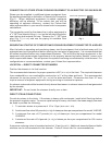
Connect the electrical supply circuit to the terminal block in the field connection box located behind the
left side panel at the rear. A 1
7
/8" (4.8 cm) diameter hole for 1
1
/2" (3.8 cm) trade-size conduit is provided
on the side of the control box. Use copper wire suitable for at least 75°C. A grounding wire must be
connected to the ground lug.
The wiring diagram is located on the door of the boiler.
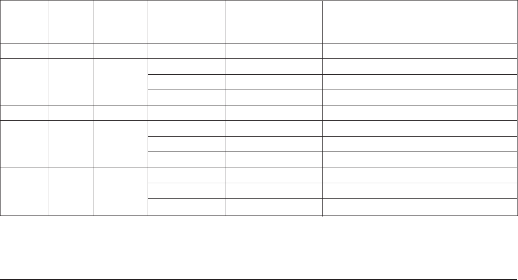
ELECTRICAL DATA
Minimum Circuit Ampacity
Volts Hertz Phase Total KW Machine Amps Maximum Protective Device
AMPS
208 60 1 24 115.4 150
24 66.6 90
208 60 3 36 99.9 125
42 116.6 150
240 60 1 24 100 125
24 57.7 90
240 60 3 36 86.6 125
48 115.5 150
24 28.9 50
480 60 3 36 43.3 70
48 57.7 90
Compiled in accordance with the National Electrical Code, ANSI-NFPA-70 (latest edition).


