


Please Do Not Return This Product To The Store. Contact your local Wayne-Dalton dealer. To find your local Wayne-Dalton dealer,
refer to your local yellow pages business listings or go to the Find a Dealer section online at www.Wayne-Dalton.com
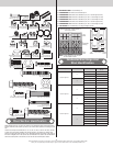
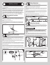
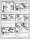
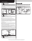
IF YOU HAVE 3” VERTICAL TRACKS:
Tighten lag screws, securing the bottom jamb bracket/bottom slot to jamb, maintain 1/2” to
3/4” spacing, between the bottom section and vertical track.
Hang counterbalance lift cable over flag angle/wall angle. Repeat same process for other
side.
2” Vertical track
spacing (3/8” to 5/8”)
3” Vertical track
spacing (1/2” to 3/4”)
Bottom
section
Floor
Track roller
Wallangle
track
assembly
Jamb
bracket
Riveted track
flag angle
shown
Riveted
flag angle
5/16” x 1-5/8”
Lag screws
Bottom
section
Track
rollers
Vertical track
assembly
Flag
angle
Lag
screw
locations
Fully Adjustable
flag angle
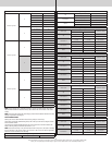
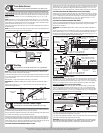
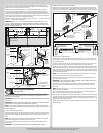
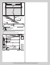
Stacking Sections
Tools: Power drill,7/16” Socket driver
13
NOTE: Make sure graduated end and center hinges are flipped down, when stacking another
section on top.
With assistance, lift intermediate I (second) section and guide the track rollers / tandem
rollers into the vertical tracks. Lower section until it is seated against bottom section. Keep
sections aligned. Repeat same process for other sections, except top section.
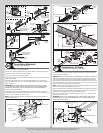
FOR GRADUATED END HINGES AND CENTER HINGES:
Starting with the outer graduated end hinges, flip the upper hinge leaf up and secure to the
section using (2) 1/4”-20 x 2-1/2” carriage bolts and (2) 1/4”–20 flange hex nuts. Repeat
same process for the center hinges.
If you have double graduated end hinges, flip the inner upper hinge leaf up and use it as a
template. Mark and pre-drill (2) 1/8” pilot holes, 1” deep into the section using a 1/8” drill bit.
Attach the upper hinge leaf to the section using (2) 1/4”-14 x 1” lag screws. Repeat same
process for other side.
IF YOU HAVE HALF CENTER HINGES:
Flip the upper hinge leaf up and use it as a template. Mark and pre-drill (2) 1/8” pilot holes,
1” deep into the section using a 1/8” drill bit. Attach the upper hinge leaf to the section using
(2) 1/4”-14 x 1” lag screws. Repeat same process for other half center hinges.
IMPORTANT: BE EXTREMELY CAREFUL NOT TO DRILL THRU THE SECTION. ONLY DRILL 1”
DEEP.
IMPORTANT: PUSH & HOLD THE HINGE LEAFS SECURELY AGAINST THE SECTIONS WHILE
SECURING WITH 1/4”-20 X 2-1/2” CARRIAGE BOLTS AND 1/4”–20 FLANGE HEX NUTS.
THERE SHOULD BE NO GAP BETWEEN THE HINGE LEAFS AND THE SECTIONS.
Center
hinge(s)
Left single
graduated end
hinge with
typical short
stem track roller
Right single
graduated end hinge
with typical short
stem track roller
(2) 1/4”-20 x 2-1/2” Carriage bolts and (2) 1/4”-20 Flange hex nuts
Intermediate I section
Bottom section
Vertical
tracks
Left double graduated
end hinge with typical
long stem track roller
Typical graduated end
hinge with typical long
stem tandem track roller
Right double graduated
end hinge with typical
long stem track roller
(2) 1/4”-14 x 1”
Lag screws
Long strut (if applicable)
Typical sections shown
Half center hinge
Upper hinge leaf
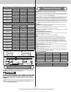
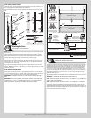
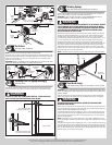
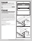
Top Section
Tools: Hammer, Step ladder, Tape measure
14
Place the top section in the opening. Temporarily secure the top section by driving a nail into
the header near the center of the door and bending it over the top section. Now, flip up the
graduated end hinge and center hinge leaves, hold tight against section, and fasten center
hinges first and end hinges last (refer to step, Stacking Sections). Vertical track alignment
is critical. For 2” track, position flag angle/wall angle between 1-11/16” (43 mm) to 1-3/4”
(44 mm) from the edge of the door; tighten the bottom lag screw. For 3” track, position flag
angle/wall angle between 2-3/16” (56 mm) to 2-1/4” (57 mm) from the edge of the door;
tighten the bottom lag screw.
Flag angles/wall angles must be parallel to the door sections. Repeat same process for other
side.
IMPORTANT: THE DIMENSION BETWEEN THE FLAG ANGLES MUST BE:
FOR 2” TRACK APPLICATIONS: DOOR WIDTH PLUS 3-3/8” (86MM) TO 3-1/2” (89 MM) FOR
SMOOTH, SAFE DOOR OPERATION.
FOR 3” TRACK APPLICATIONS: DOOR WIDTH PLUS 4-7/8” (124MM) TO 5” (127 MM) FOR
SMOOTH, SAFE DOOR OPERATION.
Complete the vertical track installation by securing the jamb bracket(s) or slots in the wall
angle and tightening the other lag screws. Push the vertical track against the track rollers so
that the track rollers are touching the deepest part of the curved side of the track; tighten all
the track bolts and nuts. Repeat for other side.
11