


Please Do Not Return This Product To The Store. Contact your local Wayne-Dalton dealer. To find your local Wayne-Dalton dealer,
refer to your local yellow pages business listings or go to the Find a Dealer section online at www.Wayne-Dalton.com
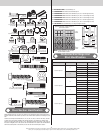
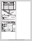
Top section
Top
section
Nail
Flag angle or
wallangle assembly
Top of flag angle or
Top of wallangle assembly
Vertical track
against rollers
Door width (2” Track)
+ 3-3/8” to 3-1/2”
Door width (3” Track)
+ 4-7/8” to 5”
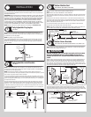
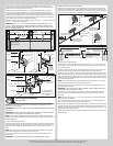
2” Track Applications:
1-11/16” to 1-3/4”
3” Track Applications:
2-3/16” to 2-1/4”
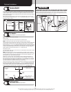
Horizontal Tracks
Tools: Ratchet wrench, 7/16” Socket, 9/16” Socket, 9/16” Wrench,
15
To install horizontal track, place the curved end over the top track roller of the top section.
Align the bottom rail of the horizontal track with the top of the vertical track. Tighten the bot-
tom rail of the horizontal track to the flag angle or wall angle with (2) 1/4”-20 x 9/16” track
bolts and (2) 1/4”-20 flange hex nuts.
Flag angle
(2) 1/4”-20 x 9/16”
Track bolts
(2) 1/4”-20
Flange hex nuts
Bottom rail of
horizontal track
Vertical
track
Wall angle
(2) 1/4”-20 x 9/16”
Track bolts
(2) 1/4”-20
Flange hex nuts
Vertical
track
Bottom rail of
horizontal track
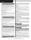
WARNING WARNING
DO NOT RAISE DOOR UNTIL HORIZONTAL TRACKS ARE SECURED AT REAR,
AS OUTLINED IN STEP, REAR BACK HANGS, OR DOOR COULD FALL FROM
OVERHEAD POSITION CAUSING SEVERE OR FATAL INJURY.
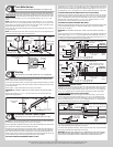
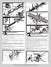
Level the horizontal track assembly.
For riveted track assembly, bolt the top rail of the horizontal track to the first encountered slot
in the flag angle using (1) 1/4”-20 x 9/16” track bolt, (1) washer and (1) 1/4”-20 flange hex
nut.
For wall angle track assembly, first bolt the angle of the horizontal track to the slots in the
wall angle using (2) 3/8”-16 x 3/4” truss head bolts and (2) 3/8”-16 hex nuts. Now secure
the top rail of the horizontal track to the wall angle using (1) 1/4”-20 x 9/16” track bolt, (1)
washer and (1) 1/4”-20 flange hex nut.
Repeat for other side.
Remove the nail that was temporarily holding the top section in place, installed in step, Top
Section.
IMPORTANT: FAILURE TO REMOVE NAIL BEFORE ATTEMPTING TO RAISE DOOR COULD
CAUSE PERMANENT DAMAGE TO TOP SECTION.
Flag angle
(2) 3/8”-16 Hex nuts
(2) 3/8”-16 x 3/4”
Truss head bolts
Top rail of
horizontal track
Wall angle
Washer
(1) 1/4”-20 Flange hex nut
(1) 1/4”-20 x 9/16”
Track bolt
Washer
(1) 1/4”-20
Flange hex nut
(1) 1/4”-20 x 9/16”
Track bolt
Top rail of
horizontal track
Adjusting Top Fixtures
Tools: 7/16” Wrench, Step ladder
16
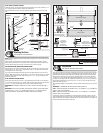
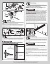
With horizontal tracks installed, you can now adjust the top fixtures.
NOTE: If your door came with two top fixtures, then one top fixture is required to be adjusted
for each side.
NOTE: If your door came with four top fixtures, then two top fixtures are required to be
adjusted for each side.
Starting on the left hand side, vertically align the top section of the door with the lower sec-
tions. Maintaining the top fixture(s) position, tighten the 1/4”-20 flange hex nuts or 1/4”-20
x 1-3/8” bolts and or 1/4”-14 x 1” lag screws to secure the top fixture(s) to the top section.
Repeat for other side
Left hand top fixture(s)
Track roller
(2) 1/4” - 20 Flange hex nuts or
(2) 1/4” - 20 x 1-3/8” bolts
Horizontal
tracks
Top section
Top
rail
Flag angle
(2) 1/4” - 14 x 1”
Lag screws
End Bearing Brackets
Tools: Step ladder, Power drill, 7/16” Socket driver
17
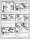
NOTE: Right and left hand is always determined from inside the garage looking out.
End bearing brackets are right and left hand.
Identify the end bearing brackets supplied with your door.
Align the bottom edge of left end bearing bracket with the top edge of the flag angle. Main-
taining this alignment, also align the right edge of the end bearing bracket with the right edge
of the flag angle.
Secure the end bearing bracket to the jamb using (3) 5/16” x 1-5/8” lag screws, as shown.
Repeat same process for the other side.
Left end bearing
bracket
Top
section
(3) 5/16” x 1-5/8”
Lag screws
Top
section
Top edge
of flag
angle
Bottom
edge
Left end bearing
bracket
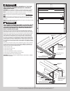
Position the left hand end bearing bracket up against the jamb and the horizontal track, as
shown. Fasten the left hand end bearing bracket to the horizontal track with (1) 3/8”-16 x
3/4” truss head bolt and (1) 3/8”-16 nut. Secure the left hand end bearing bracket to the
jamb using (3) 5/16” x 1-5/8” lag screws. Repeat same process for the other side.
(1) 3/8”-16
Hex nut
(1) 3/8”-16 x 3/4”
Truss head bolt
Upper
slot
Horizontal
track
(3) 5/16” x 1-5/8”
Lag screws
Left end bearing
bracket
Left end bearing bracket
Horizontal
track
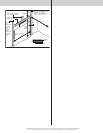
Center Bracket
Tools: Step ladder, Power drill, 7/16” Socket driver, 1/4” Torx bit, Level,
18
NOTE: Refer to the Package Contents and or Parts Breakdown to determine if your door
came with a coupler assembly.
NOTE: If your door came with a coupler assembly, the mounting surface needs to be a mini-
mum of 17” wide. The (2) center bearing brackets will need to be spaced 12” to 14” apart, at
the center of the door, as shown.
Locate the center of the door.
If your door did not come with a coupler: Mark a vertical pencil line on the mounting surface
above the door, at the center.
If your door did come with a coupler: Mark a vertical pencil line on the mounting surface
12