


Please Do Not Return This Product To The Store. Contact your local Wayne-Dalton dealer. To find your local Wayne-Dalton dealer,
refer to your local yellow pages business listings or go to the Find a Dealer section online at www.Wayne-Dalton.com
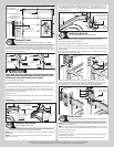
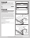
Torsion
keyed
shaft
Coupler
halves
Center bearing brackets
Torsion
keyed
shaft
Coupler
assembly
(3) 3/8” - 16
nylon hex lock
nuts
(3) 3/8” - 16 x 1-3/4”
hex head screws
Set screws
Lock nuts
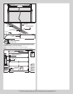
Left hand end
bearing bracket
Torsion
keyed
shaft
Torsion spring
Key
Left hand
cable drum
Set Collars
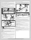
Tools: Step Ladder, 3/8” Wrench
22
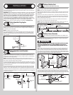
NOTE: If your door did not come with set collars, then skip this step.
Slide each of the set collars up against the inside surface of the end bearing brackets, with
the set screw facing directly away from the header. Tighten the set screw in each of the set
collars to the torsion shaft to 14-15 ft. lbs. of torque (once set screw contacts the shaft,
tighten set screw one full turn).
IMPORTANT: PRIOR TO TIGHTENING THE SET SCREWS IN THE SET COLLARS, AVOID PLAC-
ING THE SET SCREWS IN THE KEYWAYS OF TORSION KEYED SHAFT(S).
Set
collar
End bearing
bracket
Torsion
keyed shaft
End
bearing
bracket
Set
collar
Set
screw
Counterbalance
lift cable
Right
hand
cable
drum
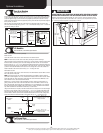
Securing Door For Spring Winding(s)
Tools: Vice Clamps
23
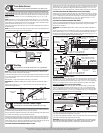
With the door in the fully closed position, place vice clamps onto both vertical tracks just
above the third track roller. This is to prevent the garage door from rising while winding
springs.
WARNING WARNING
FAILURE TO PLACE VICE CLAMPS ONTO VERTICAL TRACK CAN ALLOW
DOOR TO RAISE AND CAUSE SEVERE OR FATAL INJURY.
Vice clamps above third
track roller on both sides of
door
Bottom section
Vice clamps attached to inner
and outer rail of vertical track
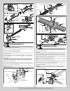
Winding Springs
Tools: Step Ladder, Approved winding bars, 3/8” Wrench
24
Position a ladder slightly to the side of the spring so that the winding cone is easily acces-
sible, and so your body is not directly in line with the winding bars.
IMPORTANT: CHECK THE LABEL ATTACHED TO THE SPRING WARNING TAG FOR THE
REQUIRED NUMBER OF COMPLETE TURNS TO BALANCE YOUR DOOR.
WARNING WARNING
PRIOR TO WINDING OR MAKING ADJUSTMENTS TO THE SPRINGS, ENSURE
YOU’RE WINDING IN THE PROPER DIRECTION AS STATED IN THE INSTAL-
LATION INSTRUCTIONS. OTHERWISE THE SPRING FITTINGS MAY RELEASE
FROM SPRING IF NOT WOUND IN THE PROPER DIRECTION AND COULD
RESULT IN SEVERE OR FATAL INJURY.
Alternately inserting the winding rods into the holes of the springs winding cone, rotate the
winding cone downward toward the floor, 1/4 turn at a time, until the required number of
complete turns for your door height is achieved. As the last 1/8 to 1/4 turn is achieved,
securely hold the winding rod while tightening both set screws in the winding cone to 14-15
ft. lbs. of torque (once set screws contact the torsion shaft, tighten screws one full turn).
Carefully remove winding rod from winding cone. Repeat for the opposite spring. While
holding the door down to prevent it from raising unexpectedly in the event the spring(s) were
over-wound, carefully remove the locking pliers from the torsion shaft and vertical tracks.
Adjustments to the number of turns stated may be necessary. If door rises off floor under
spring tension alone, reduce spring tension until door rests on the floor. If the door is hard to
rise or drifts down on its own, add spring tension.
NOTE: An unbalanced door such as this can cause garage door opener operation problems.
Torsion shaft
Winding cone
Spring
Approved
winding rods
Set screws
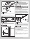
Rear Back Hangs
Tools: Ratchet wrench, Socket: 1/2” 5/8”, Wrench: 1/2” 5/8”, (2) Vice
25
IMPORTANT: HOLD THE DOOR DOWN TO PREVENT IT FROM RISING UNEXPECTEDLY IN THE
EVENT THE SPRING(S) WAS OVER-WOUND AND CAUTIOUSLY REMOVE VICE CLAMPS FROM
VERTICAL TRACKS.
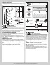
Raise the door until the top section and half of the next section are in the horizontal track
radius. Do not raise door any further since rear of horizontal tracks are not yet supported.
WARNING WARNING
RAISING DOOR FURTHER CAN RESULT IN DOOR FALLING AND CAUSE
SEVERE OR FATAL INJURY.
Clamp a pair of vice clamps onto the vertical tracks just above the second track roller on one
side, and just below the second track roller on the other side. This will prevent the door from
raising or lowering while installing the rear back hangs.
Using perforated angle (may not be supplied), (2) 5/16” x 1-5/8” hex head lag screws and
(3) 5/16” bolts with nuts (may not be supplied), fabricate rear back hangs for the horizontal
tracks. Attach the horizontal tracks to the rear back hangs with 5/16”-18 x 1 hex bolts and
nuts (may not be supplied).
NOTE: Doors heights over 8’0” or door widths over 11’0”, require an additional set of rear
center back hangs to be installed and located at the middle of the horizontal tracks, see parts
breakdown.
Using perforated angle (may not be supplied), (2) 5/16” x 1-5/8” hex head lag screws and (3)
5/16” bolts with nuts (may not be supplied), fabricate rear center back hangs for the horizon-
tal tracks. Measure and drill a 3/8” diameter hole through the center length of the horizontal
track, as shown. Attach the rear center back hangs to the horizontal tracks with (1) 3/8” truss
head bolt and (1) 3/8” nut (may not be supplied).
15