


WARRANTY xi
SPECIFICATIONS 1
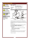
FEATURES & OPERATING CONTROLS 2
PRECAUTIONS & GENERAL INFORMATION 4
AGENCY LISTING INFORMATION 4
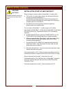
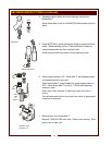
INSTALLATION 5
OPERATION 11
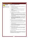
CLEANING INSTRUCTIONS 12
DELIMING INSTRUCTIONS 13
TROUBLESHOOTING SUGGESTIONS 16
PARTS & SERVICE 17
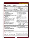
CUSTOMER SERVICE DATA 17
Thank you for purchasing this Wells Manufacturing Co. appliance.
Proper installation, professional operation and consistent maintenance of this appliance will ensure that it
gives you the very best performance and a long, economical service life.
This manual contains the information needed to properly install this appliance, and to use and care for the
appliance in a manner which will ensure its optimum performance.
TABLE OF CONTENTS
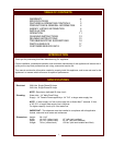
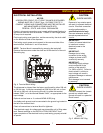
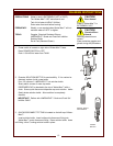
Electrical: 208 Volts, Single Phase 35 Amps
240 Volts, Single Phase 35 Amps
NOTE: Requires a dedicated 50 Amp circuit
Plumbing: Water Inlet: 1/4” Male Flare Fitting
Supply: 1/4” Female Flare supplied by a 1/4” O.D. or larger water supply line
NOTE: If water supply run from main supply line to Water-Max™ exceeds 12 feet,
a 3/8” O.D. or larger water supply line is required.
For higher capacity, hook-up to a hot water line.
IMPORTANT: This dispenser must be installed in compliance with all applicable
federal, state and local codes and ordinances.
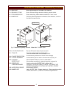
Dimensions: Height: 28-11/16”
Width: 10-1/16” (without tank) 15” (with tank installed)
Depth: 22-7/16” (without tank) 25-1/4” (with tank installed)
Weight: 74 lbs. (without tank) 150 lbs. (with tank installed and filled)
SPECIFICATIONS
INTRODUCTION
1