


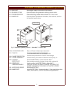
INSTALLATION (continued)
ELECTRICAL INSTALLATION
NOTICE:
A DEDICATED CIRCUIT OF AT LEAST 50 AMPS IS REQUIRED.
WIRING MUST BE AT LEAST 6 ga., SUITABLE FOR 75º C.
CONDUIT, WIRING AND CONNECTIONS MUST BE INSTALLED
AND MAINTAINED IN COMPLIANCE WITH
FEDERAL, STATE, AND LOCAL ORDINANCES.
Conduit, wiring and connections must comply with the specifications in
this manual, and with local ordinances. A 208V or 240V single phase,
50 amp circuit required.
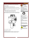
Field supply wiring must pass thru, and be secured by, the strain relief
on the bottom left side of the dispenser.
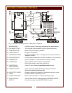
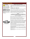
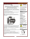
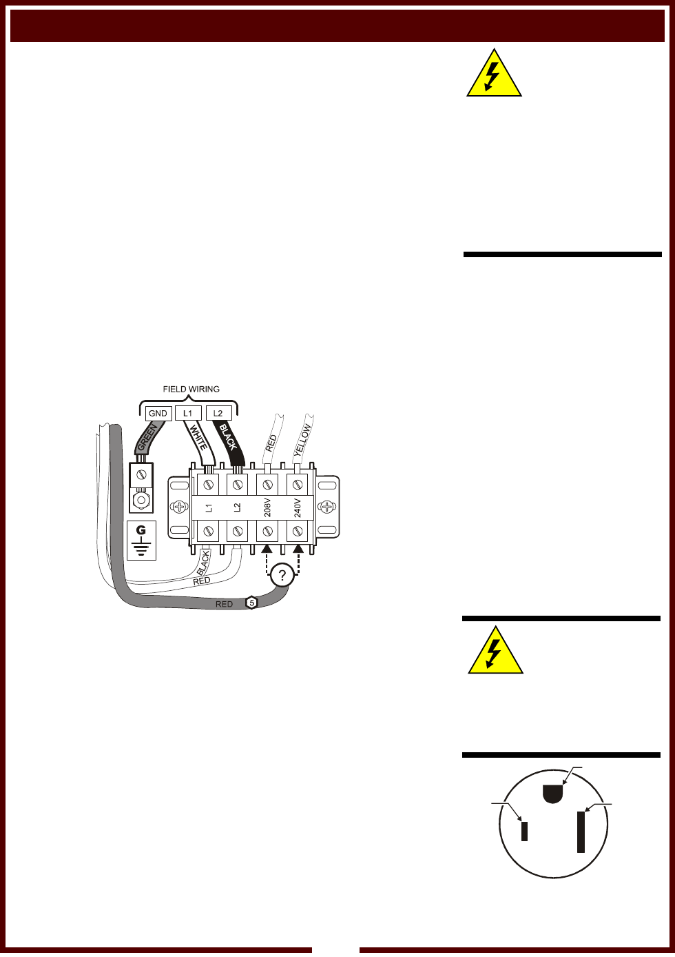
Field wiring supply power must connect to the rear-most side of the
terminal block, terminals L1 and L2 as shown.
NOTE: Terminal block is accessible by removing the tank shelf.
Remove the two screws under the shelf and lift the shelf off of the unit.
See wiring tag.
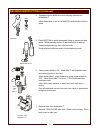
The dispenser is shipped from the factory configured for either 208 volt
or 240 volt use. It may be converted from 208 volt to 240 volt, or from
240 volt to 208 volt, use by moving Wire #11 to either the terminal
labeled “208V”, or to the terminal labeled “240V”, as appropriate for the
input voltage.
Optional cord set uses a 4’ cord and NEMA 6-50P plug.
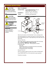
A suitable earth ground must be connected to the ground lug located to
the left of the terminal block.
Check all connections to terminal block for tightness.
Test electrical supply for voltage and amp draw while unit is filling water
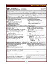
tank. Record readings on the INSTALLATION CHECKOUT form.
Upon completion of the electrical hook-up and testing, properly reinstall
all panels.
Fig. 4 Terminal Block Wiring
CAUTION:
SHOCK HAZARD
Removal of any exterior panel
will result in exposed electrical
circuits. Electrical connection
must be performed by a
qualified technician only.
Use care whenever working
around exposed electrical
circuits.
IMPORTANT:
Contact a licensed electrician
to install and connect
electrical power to the
dispenser.
IMPORTANT:
Damage due to being
connected to the wrong
voltage or phase is NOT
covered by warranty.
IMPORTANT:
Field wiring supply voltage
must correspond to the
position of red wire #11
(i.e. 208V or 240V). Failure to
match wire #11 position to
input voltage can result in
equipment damage or reduced
performance.
Such damage is not covered
by warranty.
CAUTION:
SHOCK HAZARD
Failure to connect the chassis
ground to a suitable earth
ground will result in a potential
shock hazard.
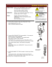
GROUND
L1
L2
NEMA 6-50P
Fig. 5 NEMA 6-50P Plug
7