


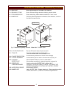
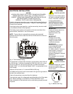
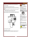
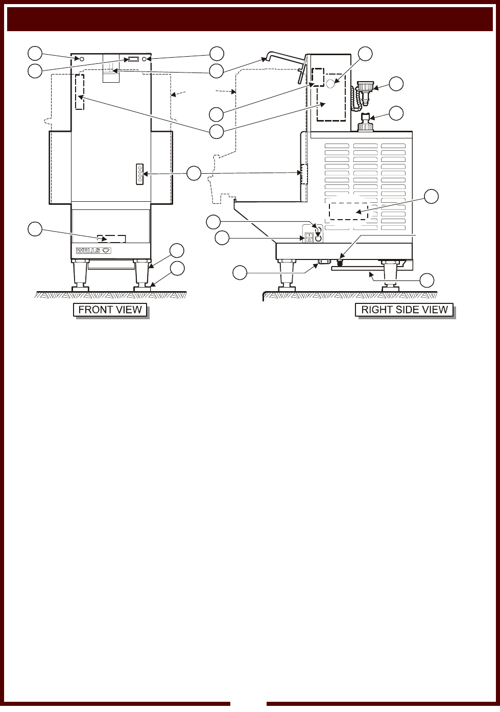
FEATURES & OPERATING CONTROLS
TANK
(Typical)
13
79
28
29
82
73
17
45
WATER-MAX™
WATER INLET
FITTING
74
44
1
71
42
26
78
90
64
25
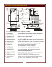
Fig. 1 Features & Operating Controls - Water Max™ Dispenser
1. STRAIN RELIEF
13. DELIMING FITTING
17. TANK INDICATOR
25. POWER SWITCH
26. DISPENSER NOZZLE
28. ADJUSTABLE LEG
29. RUBBER FOOT
42. CONNECTOR
44. CONTROLLER
CIRCUIT BOARD
45. TERMINAL BLOCK
64. AIR OUTLET GUARD
71. FUSES
73. POWER INDICATOR
74. TANK POSITION
SWITCH
(Left Side, Bottom) Field supply wiring enters the appliance here.
Tank mounted quick disconnect fitting for deliming procedure.
Glows when tank is properly installed.
Energizes the appliance.
Hot water is dispensed here. Inserting water tank lowers nozzle into
“dispense” position.
Provides required clearance to counter, and allows unit to be leveled.
Allows Water-Max™ to operate without “walking” or sliding.
Allows WATER TANK to connect to Water-Max™.
Also provides power to keep tank contents hot.
(Inside left side) Access by qualified technician only.
(Inside, under tank shelf) Field supply wiring connects here.
Access by qualified technician only.
Provides a measure of protection for transformer cooling air outlet.
Provide protection for electrical circuits.
Glows when Water-Max™ is ON and operating normally.
Held ON when WATER TANK depresses DISPENSER NOZZLE.
Unit will not operate unless WATER TANK is in place.
2