


2-1
© 1997 Whirlpool Corporation
Cooking Products Service Manual
Original March, 1997 4322167
Page 2-1
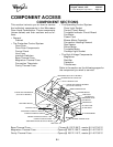
COMPONENT SECTIONS
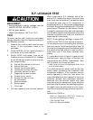
Base Thermal Fuse ................................................. Closes @ 133˚F/56˚C, resets @ 104˚F/40˚C.
Magnetron Thermal Fuse ...................................... Opens @ 228˚F/109˚C, resets @ 140˚F/60˚C.
Cavity Thermal Fuse .............................................. Opens @ 230˚F/110˚C, resets @ 140˚F/60˚C.
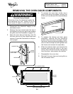
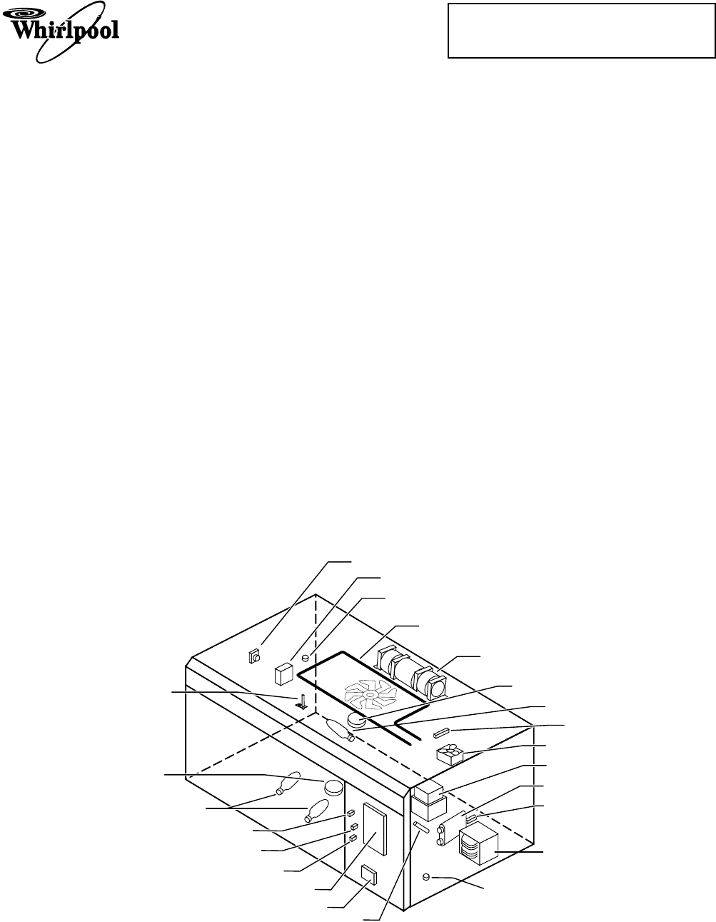
COMPONENT ACCESS
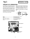
This section instructs you on how to service
the individual components in the Microwave
Oven Hood Combination. These components
(shown below) and their sections are as fol-
lows:
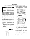
• General
Cabinet
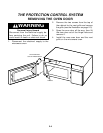
• The Protection Control System
Oven Door
Oven Door Components
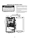
Control Panel
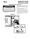
Line Fuse
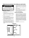
Interlock Switches
Base Thermal Fuse
Magnetron Thermal Fuse
Convection Thermistor
Cavity Thermal Fuse
• The Operating Control System
Oven Light Socket
Control Circuit Board
Turntable Indicator Circuit Board
Fan Motor
Power Cord
Blower Motor Capacitor
Convection Heating Element
Gas Sensor
Stirrer Motor
Turntable Motor
Cooktop Light Socket
• The High Voltage Components
Magnetron
Rectifier
Capacitor
Transformer
Refer to the section on the following pages for
the component you wish to service.
BLOWER MOTOR
BLOWER MOTOR CAPACITOR
FAN MOTOR
CAVITY THERMAL FUSE
CONVECTION HEATING ELEMENT
(NOT ON ALL MODELS)
HV TRANSFORMER
HV CAPACITOR
HV RECTIFIER
MAGNETRON
BASE THERMAL FUSE
LINE FUSE
CONTROL CIRCUIT BOARD
TURNTABLE INDICATOR CIRCUIT BOARD
SECONDARY INTERLOCK SWITCH
INTERLOCK MONITOR SWITCH
COOKTOP LIGHTS
OVEN LIGHT
STIRRER MOTOR
TURNTABLE MOTOR
CONVECTION THERMISTOR
(NOT ON ALL MODELS)
GAS SENSOR (NOT ON ALL MODELS)
PRIMARY INTERLOCK SWITCH
MAGNETRON
THERMAL FUSE