


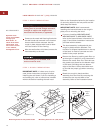
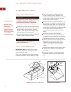
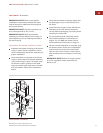
Remove the electrical box cover from the
rough-in plate. Connect black wire to power
supply black wire, white wire to power
supply white wire and green wire to green
wire or bare wire.
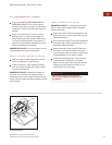
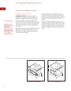
Place all wiring connections inside the elec-
trical box and reinstall on the rough-in plate
in the upper right-hand corner. Make sure
that the wires are secure and that no wires
are pinched between the cover and box.
16
WOLF PRO WALL VENTILATION HOODS
PRO WALL VENTILATION HOODS
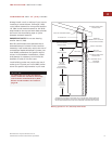
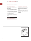
STEP 6: INSTALL WIRING
This ventilation hood must be properly
grounded. This unit should be installed by
a qualified electrician in accordance with
all applicable national and local electrical
codes.
Before servicing or cleaning unit, switch
power off at service panel and lock the
service disconnecting means to prevent
power from being switched on acciden-
tally. When the service disconnecting
means cannot be locked, securely fasten a
prominent warning device, such as a tag,
to the service panel.
Do not remove the control knob bezel to
access hood wiring; this will damage the
bezel assembly.
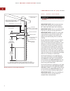
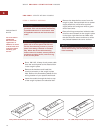
Run a 120 V AC, 15 amp circuit power cable
from the service panel to the electrical box
in the rough-in plate.
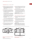
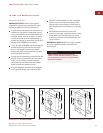
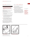
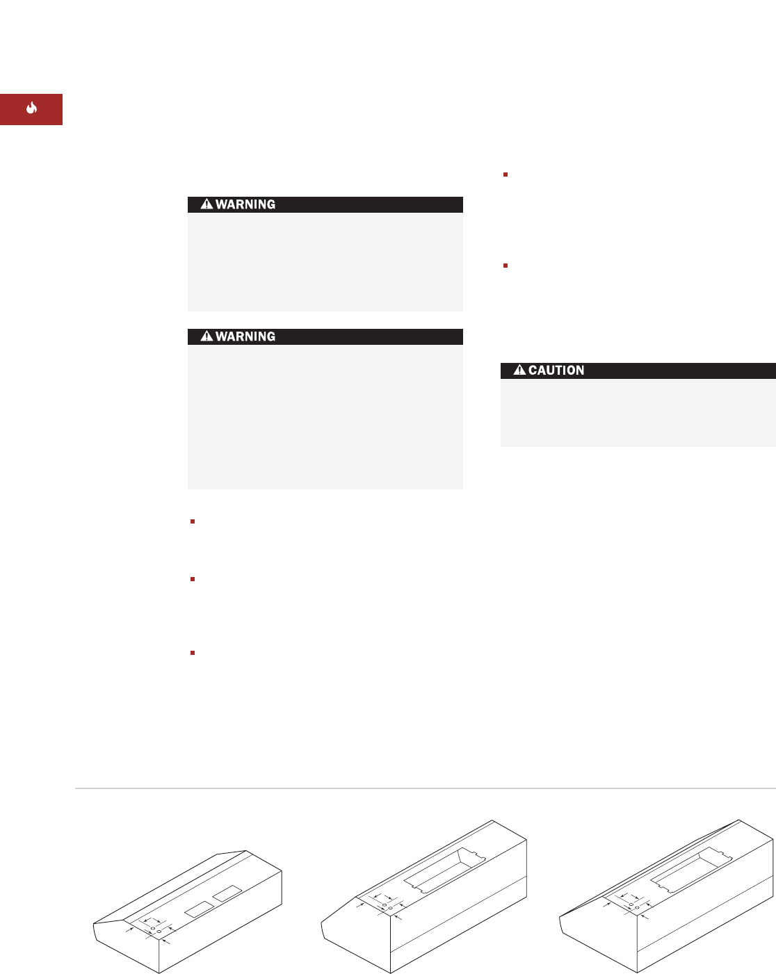
Remove the knockout and install the
conduit connector on the rough-in plate
hole. Refer to the illustrations below for the
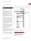
wiring location of your specific wall hood.
Insert the conduit through the hole on top
of the rough-in plate to the electrical box.
2
1
/2
" (64)
2
1
/2
" (64)
2" (51)
2
1
/2
" (64)
2
1
/2
" (64)
2" (51)
2
1
/2
" (64)
2
1
/2
" (64)
2" (51)
27" (686) deep hoods wiring locationLow-profile hoods wiring location 24" (610) deep hoods wiring location
IMPORTANT
NOTE
You must follow
all National
Electrical Code
regulations. In
addition, be aware
of local codes and
ordinances when
installing your
service.