


5
MICROMI
X
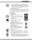
10. Power LED and Switch
The Power LED lets you know that the M608 is plugged in, turned on and all systems
are normal. The AC power on/off switch is on the rear panel of the M608.
11. Phantom Power
The Phantom Power LED indicates that 48 volts of DC phantom power is present on
the XLR microphone inputs for powering condenser microphones. Regular dynamic mics
may also be used while the Phantom Power is on. Connecting a microphone of either
type with phantom power on and the channel LEVEL up will create a large transient,
resulting in a loud, potentially damaging pop. When setting up, either turn off the AC
power, the phantom power, or set all channel levels to zero. The Phantom Power push-
button is located on the rear panel between the speaker output jacks.
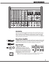
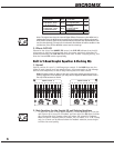
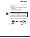
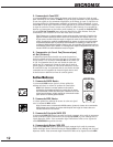
12. Tape/CD Input
Left and right RCA inputs are provided to connect a CD player, cassette player or other
stereo source to the mixer. These inputs are routed directly to the main bus, the Tape/CD
control adjusts the amount of signal.
13. Mute 1-6 Switch
The M608 includes a feature that enables users to instantly mute channels 1-6. Depressing
the Mute 1-6 switch will mute channels 1-6 signals being sent to the Left, Right, Mon and
EFX busses (the signals from these channels will still be sent to the record bus and will not
be muted. Channel 7/8 will remain active, leaving this channel open for allowing a micro-
phone or CD player, cassette player or other stereo source to be heard over the Left, Right,
Mon and EFX busses. This feature lets you mute the mics and instruments on stage and
still allows you to make announcements or play music during breaks. When the band returns
to perform, simply disable the mute.
Note: The Tape/CD input in the master section also remains active. While muted, the
Mute LED flashes at a slow rate (long on/short off) and the clip LEDs of all the muted
channels alternate long off/short on.
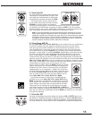
14. Amp Assign Switch
The MAIN controls determine the level of the signal routed through the Amp Assign switch:
i. In the Left/Right position, the Amp Assign switch directs the left and right MAIN
master signals through Equalizer A and Equalizer B. The signal goes to the left
and right inputs of the built-in power amplifier (Amp A and Amp B) and to the
left and right post-EQ OUT jacks.
ii. In the Main/Mon position, the Amp Assign switch sums the left and right
MAIN signals into a single, mono signal while directing it to the input of
Equalizer A, the output of which goes to both the Amp A power amp channel
and to the Post-EQ MAIN OUT jack. Additionally, the signal from the MON mas-
ter’s output is routed through Equalizer B and then to both the Amp B power
amp channel and to the MON Out jack.
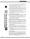
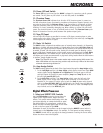
Digital Effects Processor
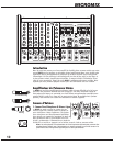
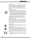
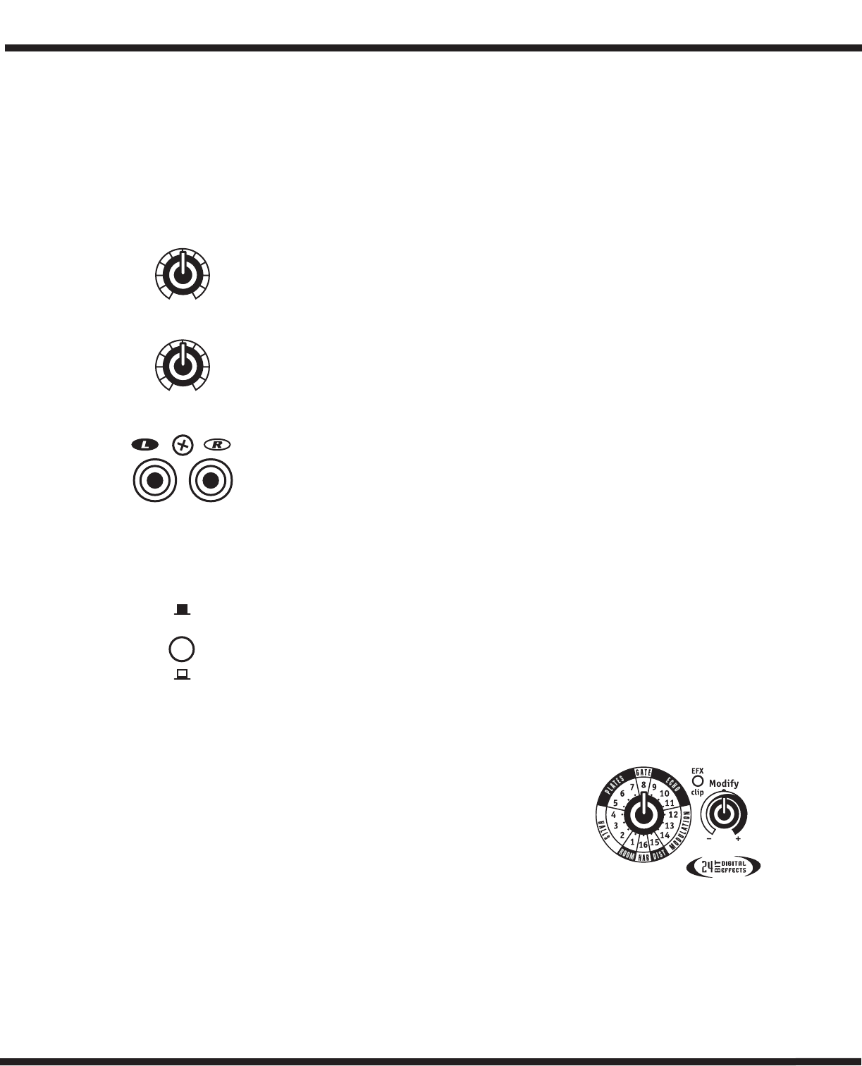
1. Select and MODIFY EFX Controls
Use the EFX Selection control to choose from the
sixteen 24-bit digital reverbs, delays and other
effects. This control rotates continuously, which lets
you rotate clockwise or counter-clockwise to select
the desired effect. For convenience, a table of the
effects and their variables appear later in this manu-
al and on the front panel of the M608.
Parameters for each of the effects can be changed using the MODIFY control which is
located next to the Selection control. For example, if a Hall reverb has been selected,
the MODIFY control will let you adjust the decay parameter. Choosing the Chorus effect
allows the chorus rate to be adjusted.
0
5
28
7
6
4
3
91
10
0
5
28
7
6
4
3
91
10
Rec Out
Tape/CD
Rec OUT
Tape/CD IN
Amp
Assign
Main/Mon
Left /Right