


20
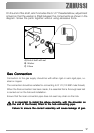
Electrical Connections
Any electrical work required to install this hob should beAny electrical work required to install this hob should be
Any electrical work required to install this hob should beAny electrical work required to install this hob should be
Any electrical work required to install this hob should be
carried out by a qualified electrician or competent person,carried out by a qualified electrician or competent person,
carried out by a qualified electrician or competent person,carried out by a qualified electrician or competent person,
carried out by a qualified electrician or competent person,
in accordance with the current regulations.in accordance with the current regulations.
in accordance with the current regulations.in accordance with the current regulations.
in accordance with the current regulations.
THIS HOB MUST BE EARTHED.THIS HOB MUST BE EARTHED.
THIS HOB MUST BE EARTHED.THIS HOB MUST BE EARTHED.
THIS HOB MUST BE EARTHED.
Electrical RequirementsElectrical Requirements
Electrical RequirementsElectrical Requirements
Electrical Requirements
The manufacturer declines any liability should these safety measuresThe manufacturer declines any liability should these safety measures
The manufacturer declines any liability should these safety measuresThe manufacturer declines any liability should these safety measures
The manufacturer declines any liability should these safety measures
not be observed.not be observed.
not be observed.not be observed.
not be observed.
This hob is designed to be connected to a 230 V 50 Hz AC electricalThis hob is designed to be connected to a 230 V 50 Hz AC electrical
This hob is designed to be connected to a 230 V 50 Hz AC electricalThis hob is designed to be connected to a 230 V 50 Hz AC electrical
This hob is designed to be connected to a 230 V 50 Hz AC electrical
supply.supply.
supply.supply.
supply.
Before switching on, make sure the
electricity supply voltage is the same as
that indicated on the hob rating plate. The
rating plate is located on the bottom of
the hob. A copy is attached on the back
cover of this book.
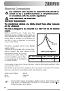
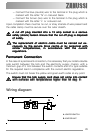
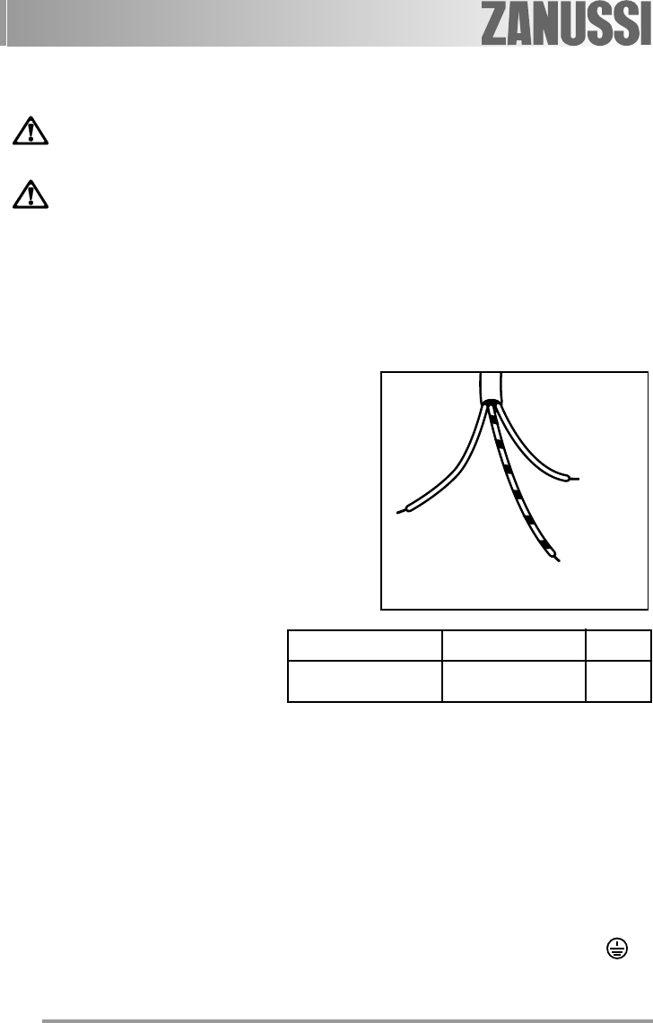
The hob is supplied with a 3 core flexible
supply cable.
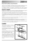
This has to be provided with a proper plug,
able to support the load marked on the
identification plate. To connect
the plug to the cable, follow the
recommendation given in Figu-
re. The plug has to be fitted in
a proper socket.
In the event of having to change the fuse, a 3amp ASTA approved (BS 1362)
fuse must be used.
Should the plug need to be replaced for any reason, the wires in the mains
lead are coloured in accordance with the following code:
Green and Yellow - Earth
Blue - Neutral
Brown - Live
— Connect the green and yellow (earth) wire to the terminal in the
plug which is marked with the letter 'E' or the earth symbol
or
coloured green and yellow.
)
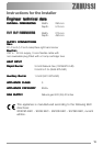
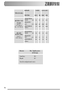
Neutral
Earth (yellow/green)
Min. size Cable/flex Cable / flex type Fuse
0.75 mm
2
H05 V2V2-F (T90) 3 A