


electrolux 59
59
Instructions for the Installer
The instructions given below are designed
specifically for a qualified installer and
should aid him or her to perform all installa-
tion, adjustment, and maintenance
operations with absolute precision and in
compliance with all current legislation and
regulations. We strongly recommend that all
operations for the installation of your cooker
be carryed out by Qualified Personnel in
accordance with existing rules and
regulations.
Electrical connection
Prior to making the electrical connection, make sure that:
— the protection fuse and the domestic wiring
system are suitable to carry the total electric load of the
oven (see rating plate);
— your domestic wiring system has an efficient
earth connection in compliance with rules and laws in
force;
— the wall socket or the omnipole switch used for
the electrical connection can easily be reached after the
oven is built in.
This appliance is delivered without an electric supply cable,
therefore, you will have to fit to it a supply cable with standard
plug, suitable for the total electric load shown on the rating plate.
The plug is to be inserted into a suitable wall socket. If you
require a direct connection to the electric network (mains), it
will be necessary to fit between the appliance and the mains an
omnipole switch, with a minimum gap between contacts of 3
mm, suitable for the required load and in compliance with rules
in force. The green & yellow ground wire must not be
interrupted by the switch, and should be 2-3 cm longer than the
phase and neutral wires. The supply cable must in all cases
be laid out in such a way as to ensure that it does not reach at
any given point a temperature 50°C higher than the ambient
temperature.
Suitable power supply cables are the following types,
considering the respective necessary section of cable: H07
RN-F, H05 RN-F, H05 RR-F, H05 VV-F, H05 V2V2-F (T90),
H05 BB-F.
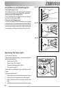
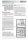
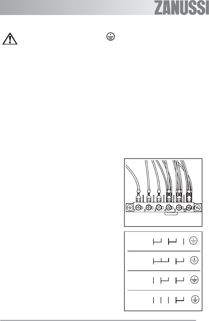
Connecting the terminal board
The appliance incorporates an easily accessible 6-pole
terminal board whose jumpers (bridges) are already pre-set for
operation on 400 V tri-phase with neutral wire (Fig. 24). In
case a different mains voltage is present, the jumpers on the
terminal board must be rearranged as shown in the diagram
(Fig. 25). The ground cable must be connected to terminal
. After connecting the supply cable to the terminal board,
secure it with a junction clamp.
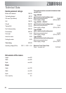
Electrical connection with the hob
This oven can be connected to hobs indicated in the
paragraph "Technical data". The socket for connecting the
hob is located at the top of the oven cabinet. The hobs
come complete with connecting leads for the hot plates/
heat areas and ground cable; these leads feature plug-in
connectors. Connection of the hob to the oven is carried
out by plugging-in these connectors to the corresponding
oven socket.
The plug-to-socket connection design is such as to
prevent possible wrong plugging-ins.
The Manufacturer disclaims any liability in case
these accident-preventing rules are not observed.
230V 3~
1 2 3 4 5
L1 L2 L3 PE
230V 1~
1 2 3 4 5
L1 N PE
400V 2N~
1 2 3 4 5
L1 L2 N PE
400V 3N~
1 2 3 4 5
L1 L2 L3 N PE
FO 0330
Ø 4x2,5mm²
Ø 3x2,5mm²
Ø 4x2,5mm²
Ø 5x1,5mm²
Fig. 24
Fig. 25