16
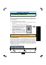
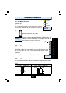
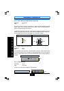
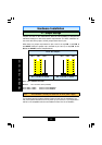
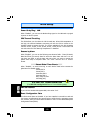
2.4.6. Floppy Disk Drive (FDC)
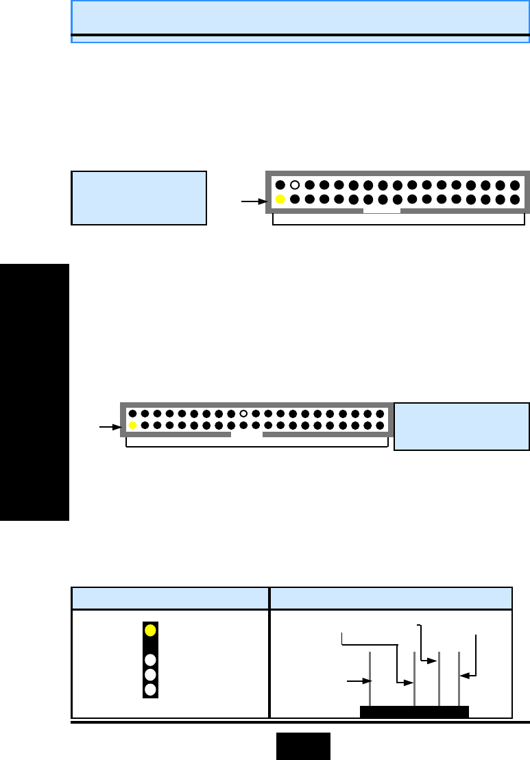
Connector: CN 8
Type: 34 pin block
The FDC connector can support two Floppy drives. It is located at the front of the
mainboard. To connect, use the ribbon-cable that has been provided. Make sure
that the red strip is connected to PIN 1 of the connector.
PIN 1
17 PINS
Top View of a
Floppy Disk Drive
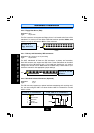
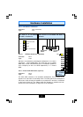
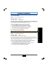
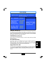
2.4.7. Primary and Secondary IDE connectors
Connector: CN 9 (primary)/ CN 10 (secondary)
Type: 40 pin blocks
The 810T mainboards all have two IDE connectors: a primary and secondary.
Each IDE connector can support two IDE drives. These mainboards can therefore
support up to four IDE devices each. If you install two hard drives, you need to
configure the second drive to slave mode in the BIOS setup
.
Please refer to your
hard drive manual for the appropriate jumper settings.
PIN 1
20 PINS
Top View of an IDE
Connector
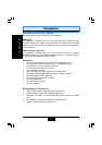
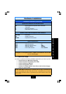
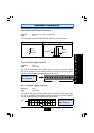
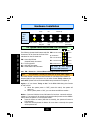
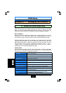
2.4.8. Standard Infrared Connector (Optional)
Connector: CN 12
Type: 5 pin
The SIR connector supports an optional wireless transmitting and receiving mod-
ule. You must configure UART 2 to select whether UART 2 is directed for use with
COM 2 or IrDA.
1 5V DC
2 No Connection
3 IR Reciever
4 Ground
5 IR Transmitter
Top View of an IR Connector
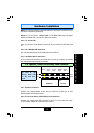
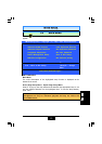
5V DC
IR Receiver
Ground
IR Transmitter
Front View of an IR Connector
Hardware Installation
Hardware Installation
Hardware Installation