21
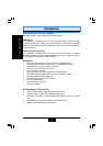
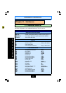
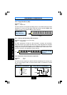
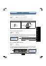
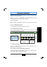
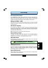
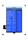
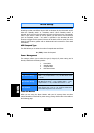
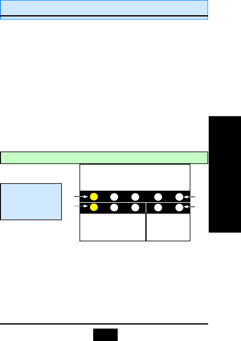
2.6.1. Speaker Connector
Connect your chassis speaker to this five pin connector. It allows you to hear
systems beeps and warnings sound.
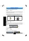
2.6.2. Front Panel Power LED and Key-Lock Connector
Connect your chassis Power LED connector to pins 1-3. If your chassis has a Key-
Lock connector, attach the connector to pin 4 and 5.
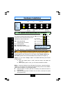
Mode 2:
Press and hold the Power ON button for more than 4 seconds, the sys-
tem will be completely powered off.
Option 2: If
you choose “
Instant OFF
.” In the BIOS CMOS Setup, the power
switch will operate like a normal ON / OFF Power button.
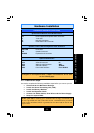
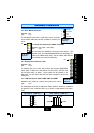
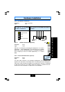
2.5.2. TL: Turbo LED
When you push the Turbo button on the front of your Chassis, this LED will come
on.
2.5.3. HL: IDE HDD LED Connector
Any read and write activity by the HDD will turn this LED on.
2.5.4. RS: Reset Button Connector
If you connect this connector, you will be able to reset you computer by pressing
the reset button at the front of the chassis.
2.
2.
2.
6
6
6
.
.
.
Speaker, Power LED and Key
Speaker, Power LED and Key
Speaker, Power LED and Key
-
-
-
Lock Connector
Lock Connector
Lock Connector
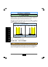
+5V DC
+5V DC
No Con-
nector
Ground
No Con-
nector
Ground
Speaker
Signal
Keyboard
Signal
No Con-
nector
Ground
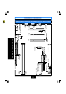
SPEAKER
POWER LED KEY LOCK
PIN 1
PIN 1
PIN 5
PIN 5
Top View of the
Speaker, Power LED
and Key-Lock Con-
nector
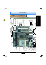
Hardware Installation
Hardware Installation
Hardware Installation