EPSON Stylus Color 900 Revision C
Disassembly and Assembly Disassembly Procedures 125
9. Turn the parallelism adjustment bushing to the left to align the
bushing with the cutout in the left frame, then pull the parallelism
adjustment forward.
10. Shift the whole carriage guide shaft to the right to release the joint at
the left end, then remove the carriage guide shaft and carriage unit
together.
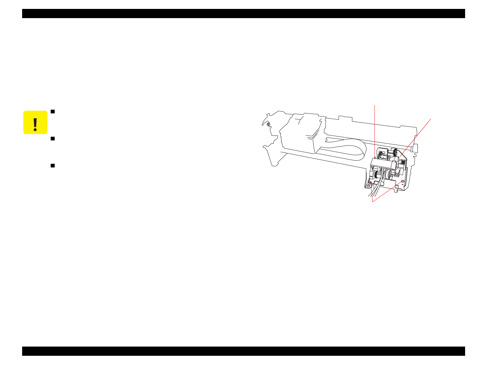
4.2.7.11 Pump Unit Removal
1. Remove the printer mechanism. (See Section 4.2.2.)
2. Remove three screws securing the pump unit and remove the pump
unit along with the frame.
Figure 4-42. Pump Unit Removal
CAUTION
After removing/replacing the Carriage Unit (Carraige
Guide Shaft), perform any necessary adjustments.
(See Table 4-1)
When removing the carriage guide shaft, pay
atttention to the oil pad as it will come off the
carriage.
When lubricating the carriage guide shaft, be sure to
follow the correct order by referring to Chapter 6.
Screws securing the Pump Unit
Pump Unit
Screws securing the Pump Unit


