EPSON Stylus Color 900 Revision C
Troubleshooting Overview 98
Table 3-33. Cleaning does not Solve the Print Problem (continued)
Unlike the previous products, the procedure after head replacement is
precisely specified. Therefore, be sure to follow the steps in Table 3-34
exactly. The background of the procedure is explained after the table.
Table 3-34.
Ink End Error Occurs after Printhead Replacement
Step Check Point Action
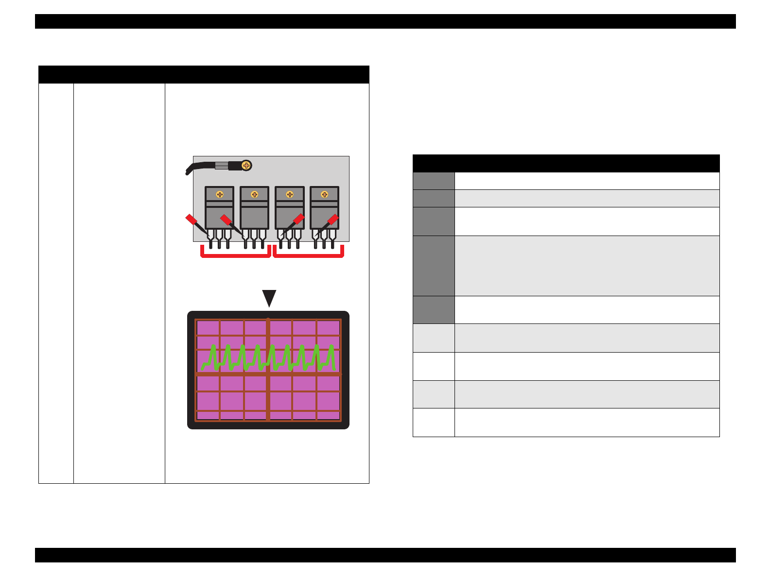
9 Is the head driving
pre-driver defective?
If a trapezoid waveform is not output in the
previous step, check all the power transistors (Q3 -
Q6) for base waveforms. Like the head transistor
in Step 8, the power transistors also output
trapezoid waveforms, but are input from the pre-
driver side.
If the waveforms are not output correctly, replace
the IC15/16 or C265 Main board. If the waveform is
output correctly, replace the corresponding power
transistor.
TH
Heat Sink
Q4
Q3
Q6
Q5
D2082B1382
D2082
B1382
B
E
T r fo r th e
black nozzles
T r fo r th e
color nozzles
20V
2
µ
Step Action
1 Turn the printer power off.
2 Replace the printhead.
3 Turn the printer back on. (The printer is in No Ink Cartridge
condition.)
4 Keep the Load/eject button pressed down for several seconds.
The printer enters the I/C replacement sequence. (The printer
moves to the black ink cartridge replacement position first, then to
the color cartridge replacement position if the Load/Eject button is
pressed.)
5 Input a 21-digit head IC. (Refer to Chapter 4 “Adjustment” for
details.)
6 Perform the initial ink charge operations. (Refer to Chapter 4
“Adjustment” for details.)
7 Perform the head angle adjustment. (Refer to Chapter 4
“Adjustment” for details.)
8 Perform the Bi-D adjustment. (Refer to Chapter 4 “Adjustment” for
details.)
9 Perform the Uni-D adjustment. (Refer to Chapter 4 “Adjustment”
for details.)


