iVIEW-100 Series user’s Manual, 2006, v2.0 ----- 18
2.5 Pin assignment of cables
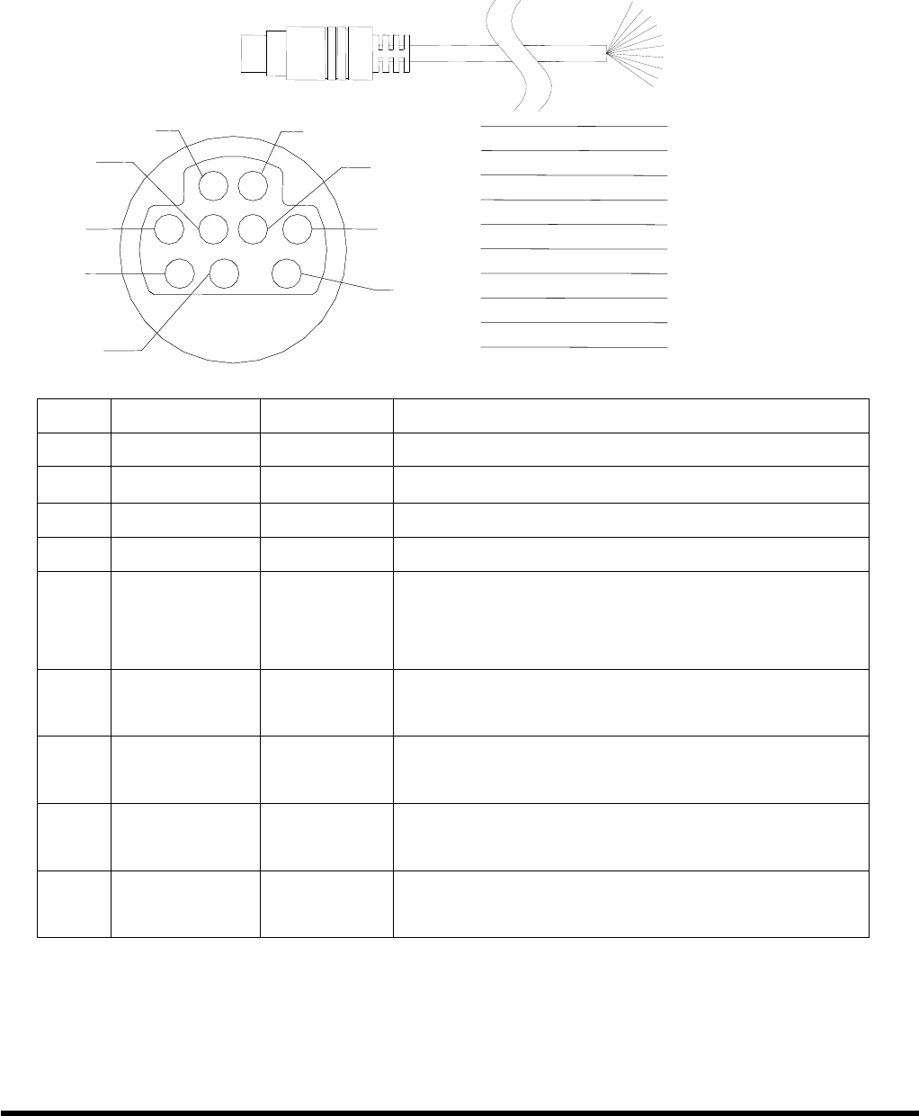
2.5.1 Pin assignment of CA-M910 cable
2
1
5
3
7
4
8
6
9
2
1
5
3
7
4
8
6
9
1
White
2
Gray
3
Yellow
4
Brown
5
Green
6
Black
7
Light Blue
8
Red
9
Blue
10
Cable Shelding
1
White
2
Gray
3
Yellow
4
Brown
5
Green
6
Black
7
Light Blue
8
Red
9
Blue
10
Cable Shelding
Pin
Name Color Description
1
DI1 White
Digital Input,3.5V~30V,channel1
2 DI2 Gray
Digital Input,3.5V~30V,channel2
3 DI3 Yellow
Digital Input,3.5V~30V,channel3
4 DI4 Brown
Digital Input,3.5V~30V,channel4
5 DO PWR Green
Input Pin of external power supply for
open collector output
Note: no need for relay output
6 Relay1+
DO1
Black
Relay 1 Output (default setting) N.O.
Digital Output 1 (jumper setting)
7 Relay1-
DO2
Light
Blue
Relay 1 Output (default setting) N.O.
Digital Output 2 (jumper setting)
8 Relay2+
DO3
Red
Relay 2 Output (default setting) N.O.
Digital Output 3 (jumper setting)
9 Relay2-
DO4
Blue
Relay 2 Output (default setting) N.O.
Digital Output 4 (jumper setting)
Wiring:
Signal Ground: All digital inputs and outputs (except relay
outputs) signal grounds are the same as the grounds of power
used by the module.
Shielding


