. A complete Parts List is available at www.MillerWelds.com
OM-217 455 Page 37
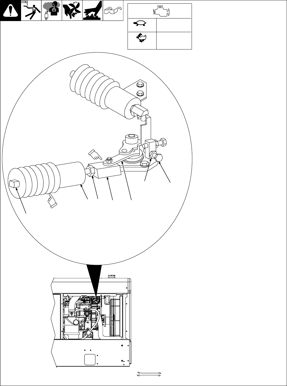
C. Making Engine Speed Adjustments
Ref. 804 250-A / 801 963
. Before adjusting engine speed, verify
throttle solenoid is installed properly
(see Section B on previous page).
Check engine speeds with a tachometer
(see table). If necessary, adjust speeds as
follows:
Start engine and run until warm. Turn V/A
control to max.
Adjusting Idle Speed
Turn Engine Control switch to Run/Idle
position.
1 Throttle Solenoid
2 Idle Speed Jam Nut
3 Plunger
4 Throttle Link
5 Throttle Lever
Loosen jam nut. While holding throttle link
with a 3/8 in wrench, turn plunger clock-
wise to increase idle speed or counter-
clockwise to decrease idle speed.
. After adjusting idle speed, verify the
throttle link is parallel with the throttle
lever. If necessary, loosen the idle
speed jam nut and reposition the
throttle link.
. Do not twist solenoid boot while ad-
justing engine speed.
Tighten jam nut.
Adjusting Weld/Power Speed
Start engine and run until warm. Turn V/A
control to max.
6 Weld Speed Jam Nut
7 Adjustment Screw
Turn Engine Control switch to Run posi-
tion. Loosen nut and turn screw counter-
clockwise to increase speed. Turn screw
clockwise to decrease speed. Tighten nut.
2375−2450 rpm
39.6−40.8 Hz
3675−3750 rpm
61.3−62.5 Hz
3/8, 7/16 in
10, 14 mm
Tools Needed:
2
3
67
1
Be sure throttle link
is parallel with
throttle lever.
Do not twist
solenoid boot
while adjusting
engine speed.
45
Idle
Weld/Power


