70
PRELIMINARY
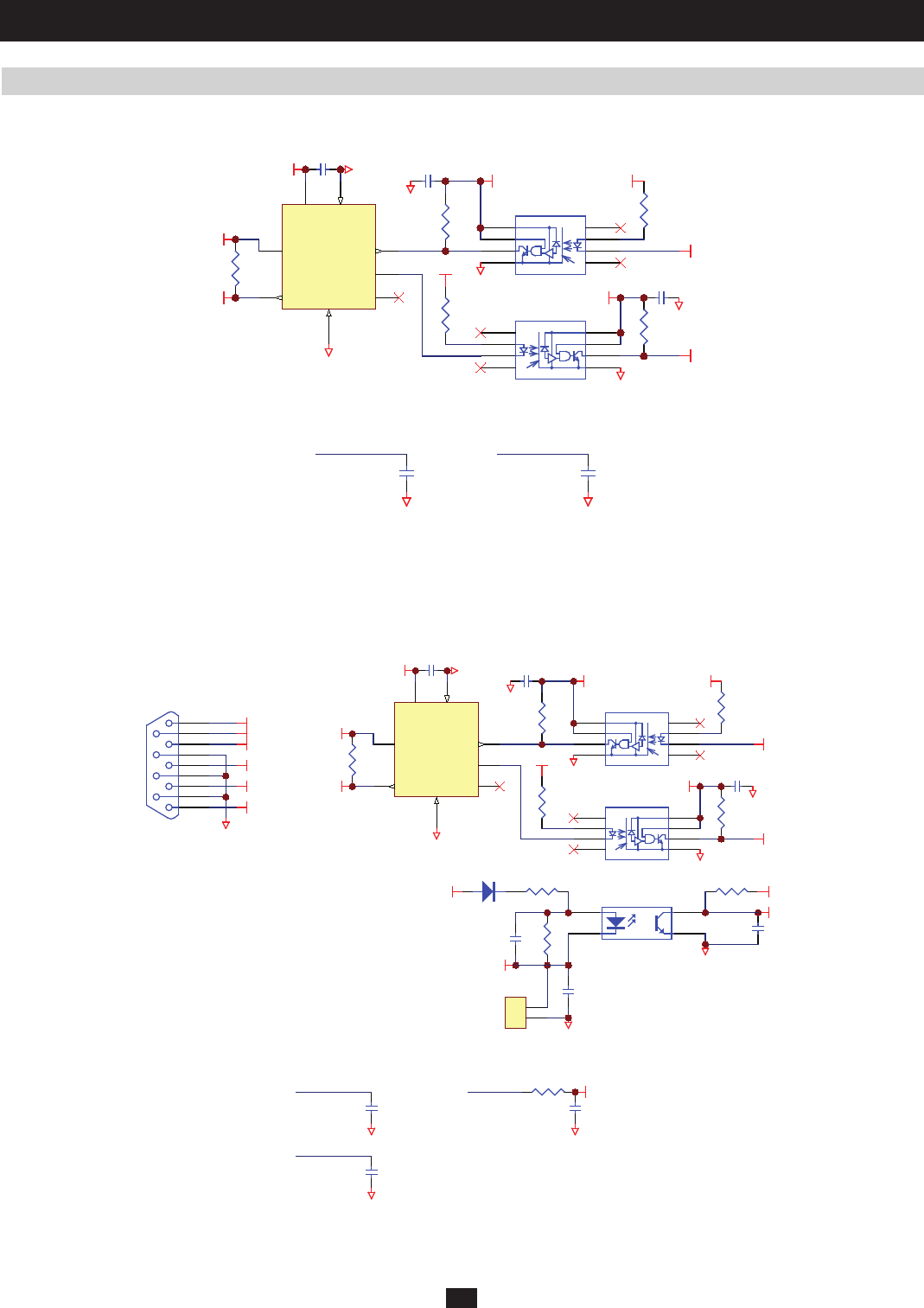
2 Theory of Operation (continued)
2.21 Control Circuit for Power Module (continued)
Located on NH-SYS-R board (Circuit for RS232, Output Dry Contact, Parallel Port, Connector to connect with each Power Module,
Circuit for 2 Slots)
Control Circuit for External Parallel
Located on NH-SYS-R board (Circuit for RS232, Output Dry Contact, Parallel Port, Connector to connect with each Power Module,
Circuit for 2 Slots)
2
3
5
6
7
8 1
4
SHIELD
UR9
RR1 4
5VS5VSF
G4
CR1 4
G4
RR1 5
GND
2
Rs
8
RXD
4
CANH
7
TXD
1
CANL
6
VCC
3
Vref
5
UR8
CR1 2
5VSF G4
2
3
5
6
7
81
4
SHIELD
UR11
RR2 1
5VSF
G4
5VS
CR1 7
G1
RR2 2
G1
CANM_TX
CANM_RX
CANH- M
CANL-M
RR1 7
Located on NH-SYS-M board (System MCU and Control Circuit)
Located on NH-SYS-M board (System MCU and Control Circuit)
(134)
CM106
G1
(135)
CM109
G1
CANM_TX CA NM_ RX
(g) CAN bus is the communication bus for load sharing, as well as the synchronization of signals between the system and its power modules.
(h) CAN bus is the communication bus for load sharing, and also synchronizes signals between the two systems.
(i) TOMBYP is the status of the manual bypass switch on the system frame. When the manual bypass switch turns on, MCU can detect its status
via TOMBYP_I(6) and auto-transfer to bypass the mode and its alarm.
2
3
5
6
7
8 1
4
SHIELD
UR2
RR3
5VS5VSF
G4
CR2
G4
RR4
GND
2
Rs
8
RX D
4
CANH
7
TXD
1
CANL
6
VCC
3
Vr ef
5
UR1
CR1
5VSF G4
2
3
5
6
7
81
4
SHIELD
UR5
RR7
5VSF
G4
5VS
CR6
G1
RR1 1
G1
CA NS_ T X
CA NS_ RX
CANH- S
CANL-S
RR5
Parallel Port
TOBYP
TOINV
TOMBYP
CA NL - S
CANH- S
SYNC_BUS
1
6
2
7
3
8
4
9
5
CN R14
G4
RR1 0 2
+12VSF
RR1 0 7
CR6 6
RR1 0 3
5VS
CR6 5
1
2
4
3
UR43
G1
TOMBYP
#TOMBYP_I
CR7 3
1
2
CN R13
G4
DR15
(136)
CM9 5
G1
(137)
CM100
G1
CANS_TX
CANS_RX
(6)
RM146
CM102
G1
#TOMBYP_I
TOMBYP_I


