


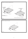

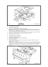
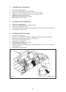
N. TO REMOVE ELEMENTS (RH OVENS)
1. Isolate from electrical supply.
2. Proceed as TO REMOVE OVEN AND BROILER LINERS’.
3. Remove oven base panel (1) screws at the rear of the oven.
4. Lift out base panel.
5. Remove oven element fixing screws (2) at the rear of the oven and flex elements to remove
from location bracket, pull forwards to expose terminal connections.
6. Remove connection, make sure they do not fall down the back of the appliance.
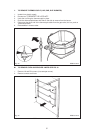
NOTE: RH TOP OVEN: has an element above the roof liner, remove in the same way as
for base elements.
7. Re-assemble in reverse order.
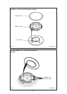
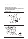
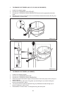
O. TO REMOVE FAN OVEN ELEMENT
1. Isolate from electric supply.
2. Proceed as ‘TO REMOVE OVEN LINERS’.
NOTE: You will only need to remove one side.
3. Remove (4) fan cover fixing screws and withdraw panel.
4. Remove 3 screws securing element to frame and carefully withdraw element until access
can be made to the electrical terminals.
5. Disconnect terminals taking care not to allow the cable to fall down the rear of the
appliance.
6. Re-assemble in reverse order.
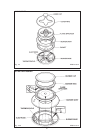
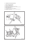
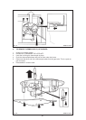
P. TO REMOVE OVEN FAN
1. Isolate from electric supply.
2. Proceed as ‘TO REMOVE OVEN ELEMENT’.
3. Remove 4 fixing screws securing fan assembly to frame.
4. Withdraw fan assembly sufficiently to gain access to motor electrical terminals and
disconnect cables.
5. Remove fan blade.
NOTE: Fan blade fixing nut is LH thread.
6. Remove motor from mounting plate screws.
7. Re-assemble in reverse order.
58