


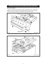

ELECTRICAL CONNECTION IS LOCATED AT THE TOP RIGHT HAND SIDE OF THE
APPLIANCE, BEHIND SIDE PANEL. DURING INSTALLATION REMOVE THE RIGHT HAND
SIDE PANEL TO CONNECT ELECTRICAL SUPPLY.
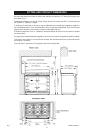
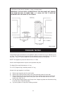
Remove 6 screws securing side panel to gain access to mains terminal. See Fig. 3 for location
of cover.
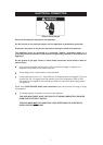
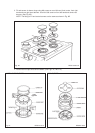
Remember
that the mains electrical cable must be routed through the grommet at the rear right
hand side of the cooker near the top via a UL listed strain relief bracket, before connecting to the
mains terminal connection.
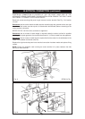
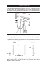
REFER TO FIG. 2 & 2A for wire connection to appliance.
Remember
that an excess of cable length is required inside the cooker to allow for possible
servicing of the spark generator, there should be at least 31” (0.78m) of cable from the appliance.
Remember
that an excess of cable length is required behind the cooker for the withdrawal of the
cooker from between the kitchen units etc.
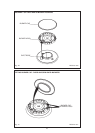
Replace the right hand side panel once electrical connection has been made and replace fixing
screws.
NOTE: Ensure the insulation card covering the mains terminal is in place, between the side
panel and mains terminal.
ELECTRICAL CONNECTION (continued)
Fig. 2
Fig. 2A
DESN 514739
DESN 512951
8