


Drawer Warmer Installation/Operation/Service Manual • 15.
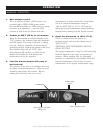
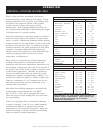
MANUAL CONTROL
THERMOSTAT and HEAT LIGHT SEQUENCE
Whenever the thermostat is turned “ON,” the heat indicator light will indicate the power ON/OFF condition of
the heating cable, and consequently, the cycling of the cabinet as it maintains the dialed cavity temperature. If
the light does not illuminate after normal start-up, the main power source, thermostat, and/or light must be
checked. If the warming cabinet does not hold the temperature as dialed, the calibration of the thermostat must
be checked. If the warmer fails to heat or heats continuously with the thermostat “OFF,” the thermostat must
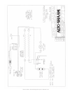
be initially checked for proper operation. If these items are checked and found to be in order, a continuity and
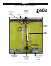
resistance check of the heating cable should be made. SEE CIRCUIT DIAGRAM.
THERMOSTAT CALIBRATION
The thermostat is precision calibrated at the factory. Normally, no adjustment or recalibration is necessary
unless the thermostat has been mishandled in transit, changed or abused while in service. A thermostat with a
sensing bulb operates on hydraulic pressure, consequently, any bending of the bulb results in a change in its
volume, and alters the accuracy of the thermostat calibration.
A thermostat should be checked or recalibrated by placing a quality, thermal indicator at the center of an empty
holding cavity. DO NOT CALIBRATE WITH ANY FOOD PRODUCT IN THE CABINET. The thermostat
should be set at 140°F (60°C), and should be allowed to stabilize at that setting for a minimum of one hour.
Following temperature stabilization, the center of the thermal swing of the air temperature within the cabinet
should approximately coincide with the thermostat dial setting.
If calibration is necessary, the calibration screw should be adjusted with great care. The calibration screw of the
thermostat is located in the thermostat dial shaft. With the shaft held stationary, a minute, clockwise motion of
the calibration screw appreciably lowers the thermostat setting. A reverse, or counter-clockwise motion
appreciably raises the thermostat setting. After achieving the desired cycling of the thermostat, the calibration
screw must be sealed. Place a few drops of enamel sealant directly on the calibration screw.
(RED NAIL POLISH OR EQUIVALENT IS ACCEPTABLE.)
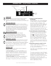
TROUBLE POSSIBLE CAUSE REMEDY
Unit does not operate. Insufficient power supply. Check power source.
Defective power cord or plug. Check and replace if necessary.
No display in electronic control. Faulty power supply board. Check line voltage for 24V across
pins 7 and 8 on the power supply board and
across terminals J9 and J10 on the electronic
control.
Faulty electronic control. Replace control.
Cannot control temperature but Faulty relay Replace relay.
sensor and electronic control
checks O.K. Heating element grounded. Replace element.
Temperature readout incorrect. Dirty or faulty sensor. Check sensor at 32°F (0°C).
If Ohm reading is 100,
Faulty control. replace display.
If Ohm reading is not 100,
replace sensor.
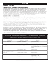
T R O U B L E S H O O T I N G C H E C K L I S T • E L E C T R O N I C C O N T R O L
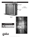
R ep ai rs s ho ul d be m ad e b y a ut ho riz ed s er vi ce a ge nt s on ly.
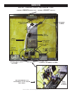
S E R V I C E