


66
www.amctechcorp.com
Available Digital I/O Pins
The number of pins available for digital I/O depends on the other options compiled into the kernel. For example,
if the EEPROM option is compiled in, then the bits from Port E bits[0-2] will not be available for digital I/O.
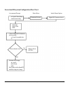
During boot up, devices that require pins for their dedicated functions will reserve them, and thus these pins
cannot be accessed by the digital I/O character driver. After all other drivers have reserved their required pins,
any remaining pins that have not been reserved will be used for digital I/O, and so a user-space program will be
able to access these pins via the character device.
In order for the pins to be reserved, a scan of applicable devices is done on boot up. Thus, the same kernel can
be used on any of the NETdimm, IOdimm, or CANdimm without having to recompile.
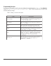
The pins are listed in Table 1 in their suggested order of use. The pins further down the list are more likely to
be used for their dedicated functions than those at the top. Table 1 also describes the respective port and bit
numbers of each class of pins, as well as their location on the backplane. Only the LCD class of I/O points and
Port G/pin5 lead to pin headers on the backplane. The remaining pins must be accessed by soldering wires to
the system or peripheral slot on the backplane. The following are notes regarding each class of pins.
The LCD class of pins are only used when an LCD display needs to be hooked up to the
dimmPCI module. Thus, they are the least likely to be used for their dedicated function, and
have the added advantage of leading to pin headers on the backplane.
The EEPROM class is only needed if an EEPROM is needed to store permanent information.
This device is normally not populated on the dimmPCI modules, making it unlikely that the
pins will be used for their dedicated function. Note that if the EEPROM is populated, those
pins cannot be used for digital I/O, even if the EEPROM driver has not been compiled in.
The SPI pins are used for peripheral interfaces such as an analog-to-digital converter. Note
that the IOdimm has its own driver for the SPI pins in order to take care of its I/O functions.
Thus, on an IOdimm the SPI pins will not be available for use by this digital I/O driver.
The ICE_DEBUG pins are the in-circuit debugger pins. These pins are more useful as
outputs, since they must not be held low on power up. PortG/Pin5 is the EMU break, and
access to this jumper pin is needed when running in rescue mode for ‘oops’. Also note that
PortG/Pin2 is the EMU IRQ, which is a non-maskable interrupt.