


8
ENGLISH
SECTION 2 - INSTALLATION
III. ASSEMBLY
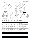
A. Top Panel and Base Pad Assembly
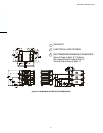
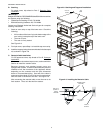
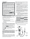
1. Install the four leg extensions onto the base pad using the
3/8"-16x1" screws, 3/8" flat washers, and 3/8" lockwashers
supplied in the Base Pad Kit. See Figure 2-6. Check that
the finished sides of each leg extension face OUTWARDS.
For domestic and standard export ovens:
One rear leg should be attached using three 3/8"-16 x 1"
screws and the 3/4" eyebolt, as shown in Figure 2-6. This
eyebolt acts as the anchor point for the restraint cable
assembly (see Part C,
Restraint Cable Installation).
2. If your oven is equipped with the lower shelf, position it in
place as shown in Figure 2-6. Check that the lip on the shelf
faces DOWN. Seal joint between leg and shelf with NSF
listed silicone.
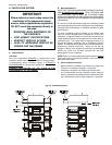
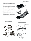
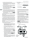
3.
For domestic and standard export ovens:
Install one caster onto each leg extension, as shown in
Figure 2-7. Use the 3/8"-16x1" screws, 3/8" flat washers,
and 3/8" lockwashers supplied in the Installation Kit. The
locking casters should be installed at the FRONT of the
oven. The non-locking casters should be installed at the
REAR of the oven.
For CE export ovens:
The Installation Kit includes four casters AND four 152mm
adjustable legs. The casters are provided to allow the oven
to be more easily moved to the installation location, and are
NOT suitable for use as part of the oven installation. Refer
to the notice at the beginning of this Section.
After the oven is at the installation location, install one
152mm adjustable leg into the center hole on the bottom
of each leg extension, as shown in Figure 2-7.
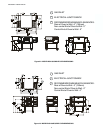
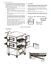
4. Install the lower oven cavity onto the base pad. See Fig. 2-7.
5. For single ovens ONLY, install the top panel using the screws
included in the base pad kit, as shown in Figure 2-7. Then,
skip ahead to Part C,
Restraint Cable Installation.
For double or triple ovens, continue on to Part B,
Stacking.
Note that the top panel should NOT be installed for double
and triple ovens until after stacking the oven cavities.
#10 x 2"
screws
Bottom oven
cavity
Top
panel
Figure 2-7 - Base and Top panel installation
NOTE:
DO NOT install top panel onto double or triple ovens
until AFTER stacking the oven cavities. See Part B, Stacking.
Figure 2-6 - Leg extension and casters installation
CE-approved
ovens:
152mm adjustable
leg MUST be used
for installation
Finished sides of
leg extension
face corner of
base pad
Lower
shelf
Locking casters -
FRONT of oven
Non-locking casters -
REAR of oven
3/8" flat
washer
3/8" lock
washer
3/8"-16 x 1"
hex screw
Assembled
base pad
Domestic and
standard export
ovens:
3/8" flat
washer
3/8" lock
washer
3/8"-16 x 1"
hex screw
3/4" eyebolt
(inside corner
of one rear leg
extension
only)
CE ovens
do not use
the
eyebolt.