


21
ENGLISH
SECTION 4 - MAINTENANCE
2. Remove the master links from each conveyor belt.
Then, roll the belts up along the length of the conveyor
to remove them from the frame.
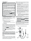
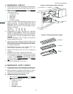
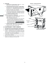
3. Remove the two conveyor adjustment screws from the
idler end of the conveyor frame, as shown in Figure 4-
4.
4. Remove the idler shaft assembly from the conveyor.
5. Pull apart the two sections of the idler shaft.
6. Clean the shafts thoroughly using a rag. Then, lubri-
cate both the extended shaft and the interior of the
hollow shaft using a light food-grade lubricant. DO
NOT lubricate the shafts using WD40 or a similar
product. This can cause the shafts to wear rapidly.
7. Before reassembling the shafts into the conveyor
frame, check that they are oriented properly.
8. Reassemble the idler shaft into the conveyor.
Make
sure that the bronze washer is in place between the
two sections of the shaft. See Figure 4-4.
9. Replace the conveyor adjustment screws as shown in
Figure 4-4. To allow the conveyor belt to be reinstalled
later, do not tighten the screws at this time.
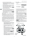
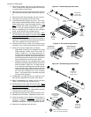
10. Loosen the set screw on both of the conveyor drive
sprockets. Then, remove the sprockets from the shaft.
11. Check the conveyor configuration as follows:
• High-speed conveyors are equipped with large
flange bearings at both ends of the shaft, as
shown in Figure 4-5. For these conveyors, re-
move the two screws that hold each bearing to the
conveyor frame. With the screws removed, lift the
end of the shaft at the front of the oven, and pull the
entire assembly free of the conveyor frame.
• Standard conveyors are equipped with bronze
bushings mounted on spacers at both ends of the
shaft, as shown in Figure 4-5. For these convey-
ors, remove the two screws that hold the bracket
to the conveyor frame. With the screws removed,
lift the end of the shaft at the front of the oven, and
pull the entire assembly free of the conveyor
frame. The brackets will be removed along with
the drive shaft assembly.
12. Disassemble and lubricate the two sections of the
drive shaft as described for the idler shaft, above.
13. Before reassembling the shafts into the conveyor
frame, check that they are oriented properly.
14. Reassemble the drive shaft into the conveyor. Make
sure that the bronze washer is in place between the
two sections of the shaft. See Figure 4-6.
15. Replace the drive sprockets. Reassemble the belts
and master links onto the conveyor.
16. Reinstall the end plugs and conveyor onto the oven.
17. Reattach the drive chains. Replace the chain cover.
18 Check the tension of the conveyor belt as shown in
Figure 2-11 (in Section 2, Installation). The belt should
lift about 1" (25mm). If necessary, adjust the belt
tension by turning the conveyor adjustment screws.
19. Replace all components onto the oven.
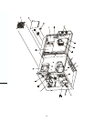
Figure 4-5 - Drive shaft configurations
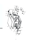
Figure 4-4 - Disassembling the idler shaft
Remove
adjustment
screws
Bronze
washer
Disassemble,
clean, and
lubricate shafts
Remove
idler
shaft
assembly
Figure 4-6 - Disassembling the drive shaft
Loosen set
screws and
remove drive
sprockets
Remove 2 screws and nuts per
side to free bearings/brackets
Flange bearing
shown (used with
high-speed
conveyors)
Disassemble,
clean, and
lubricate shafts
Flange bearing
(used with high-
speed conveyors)
Bronze bushing with
spacer (used with
standard conveyors)