


v
NOTE
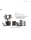
Wiring Diagrams are in Section 7 of this Manual.
The diagram for each oven is also on the lower
inner surface of its Control Console.
TABLE OF CONTENTS
Page
SECTION 1
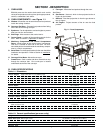
DESCRIPTION .................................................................... 4
I. OVEN USES .................................................................... 4
II. OVEN COMPONENTS .................................................... 4
A. Window ....................................................................... 4
B. Conveyor End Stop ................................................... 4
C. Eyebrows ................................................................... 4
D. End Plugs ................................................................... 4
E. Control Panel ............................................................. 4
F. Machinery Compartment and Control
Compartment Doors ............................................................ 4
G. Serial Plate ................................................................. 4
H. Conveyor Drive Motor .............................................. 4
I. Crumb Pans ................................................................ 4
J. Conveyor .................................................................... 4
K. Gas Burner ................................................................ 4
L. Blowers ....................................................................... 4
M. Air Fingers ................................................................. 4
III. OVEN SPECIFICATIONS ............................................... 4
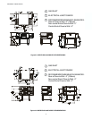
A. Dimensions ................................................................ 4
B. General Specifications ............................................. 4
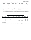
C. Electrical Specifications for Gas Ovens ................. 5
D. Gas Orifice and Pressure Specifications -
Domestic and Standard Export Ovens .................. 5
E. Gas Orifice and Pressure Specifications -
CE Ovens .............................................................................. 5
SECTION 2
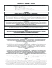
INSTALLATION ..................................................................... 6
I. INSTALLATION KIT ........................................................ 7
II. VENTILATION SYSTEM ................................................. 8
A. Requirements ............................................................ 8
B. Recommendations .................................................... 8
C. Other Ventilation Concerns ...................................... 8
III. ASSEMBLY .................................................................... 9
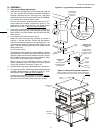
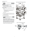
A. Top Panel and Base Pad Assembly......................... 9
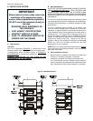
B. Stacking ................................................................... 10
C. Restraint Cable Installation .................................... 10
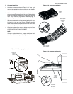
D. Conveyor Installation .............................................. 11
E. Final Assembly ........................................................ 12
IV. ELECTRICAL SUPPLY ............................................... 13
A. Additional Information - Gas Ovens ....................... 13
B. Connection ............................................................... 13
V.GAS SUPPLY................................................................ 14
A. Gas Utility Rough-In Recommendations ............... 14
B. Gas Conversion ....................................................... 14
C. Connection ............................................................... 14
TABLE OF CONTENTS
(Continued)
Page
SECTION 3
OPERATION ........................................................................ 16
I. LOCATION AND DESCRIPTION OF CONTROLS ....... 16
A. BLOWER (
)( ) Switch ....................................... 16
B. CONVEYOR (
) Switch ....................................... 16
C. Conveyor Speed Controller .................................... 16
D. Digital Temperature Controller .............................. 16
E. Machinery and Control Compartment ................... 16
Safety Switches ................................................................. 16
II. NORMAL OPERATION, STEP-BY-STEP ..................... 17
A. Daily Startup Procedure ......................................... 17
B. Daily Shutdown Procedure ..................................... 17
III. QUICK REFERENCE: DIGITAL TEMPERATURE
CONTROLLER ........................................................... 18
SECTION 4
MAINTENANCE .................................................................. 19
I. MAINTENANCE - DAILY .............................................. 19
II. MAINTENANCE - MONTHLY ....................................... 20
III. MAINTENANCE - EVERY 3 MONTHS ........................ 20
IV. MAINTENANCE - EVERY 6 MONTHS ....................... 22
SECTION 5
PARTS LIST ........................................................................ 23
I. KEY SPARE PARTS KIT .............................................. 23
II. INSTALLATION KIT ...................................................... 25
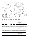
III. PANELS, END PLUGS AND WINDOW ....................... 27
IV. CONTROL COMPARTMENT ...................................... 29
V.MACHINERY COMPARTMENT AND GAS TRAIN ..... 31
VI. REAR COMPARTMENT AND BLOWERS ................. 33
VII. SINGLE-BELT CONVEYORS ..................................... 35
VIII. SPLIT-BELT CONVEYORS ....................................... 37
SECTION 6
ELECTRICAL WIRING DIAGRAMS ................................... 39
I. WIRING DIAGRAM, BG2136 GAS OVEN
(DOMESTIC & STD. EXPORT VERSION),
208/240V, 50/60 Hz, 1 Ph ........................................... 39