


10
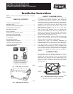
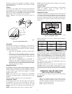
If the integrated control LED of the unit is flashing, this means the unit sensors detected a problem. See the table below to know where on the
unit the problem occurs.
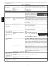
Table 5 – Troubleshooting
LED flashes GREEN. Thermistor error. Reference Table 6 for proper temperature vs. resistance relationship. If thermistor
is defective, replace the entire port assembly (fresh air from outside port).
LED flashes RED.
The door is open and the unit is not
unplugged.
Close the door and press once on the integrated control push button to reset the
unit.
Exhaust motor error. Go to Problem 5 below.
LED flashes AMBER. Damper error. Go to Problem 6 below.
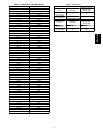
Problem: Possible causes: You should try this:
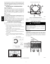
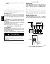
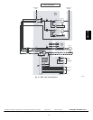
1. Unit does not work. S The circuit board may b e defectiv e. S Unplug the unit. Disconnect the main
control and the optional control(s) (if need
be). Jump G and B terminals. Plug the unit
back and wait about 10 seconds. If the
motorsrunonhighspeedandthedamper
opens, the circuit board is not defective.
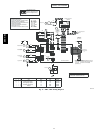
NO C NC I OC OL Y R G B
2. The damper actuator
does not work.
S The damper actuator or the integrated
damper port mechanism may be
defectiv e.
S Unplug the unit. Disconnectthe main control and the optionalcontrols(s)(ifneed
be).Wait 10 seconds and plug the unit back. Check if the damper opens. If not,
use a multim ete r and check for 24VAC o n J12-- 1 and J12-- 2 (in electrica l
compartment). If t here is 24VAC, replace the entire port assembly.
NOTE: It is normal to experience a small delay (7--8 seconds) before detecting
the 24VAC signal at starting --up. This signal will stay during 17-- 18 seconds
before disappearing.
S The circuit board may be defective. S If there is no 24VAC, replace the circuit board.
3. The wall control does
not work OR its indi -
cator flashes.
S The wires may be in reverse position. S Ensure that the color coded wires have been connected to their work OR its
indicator flashes. appropriate places.
S The wires may be broken. S Inspect every wire and replace any that are damaged.
S The wire in the wall OR the wall. S Remove the wall control and test it right beside the unit using another control
may be defective. shorter wire. If the wall control works there, change the wire. I f
it does not, change the wall control.
4. The dehumidistat
does not work OR
the 20--minute. push--
button timer does not
work OR its indicator
light does not stay
on.
S The wires may be in reverse position. S Ensure that the color coded wires have been connected to their appropriate
places.
S The dehumidified or push button may be
defectiv e.
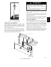
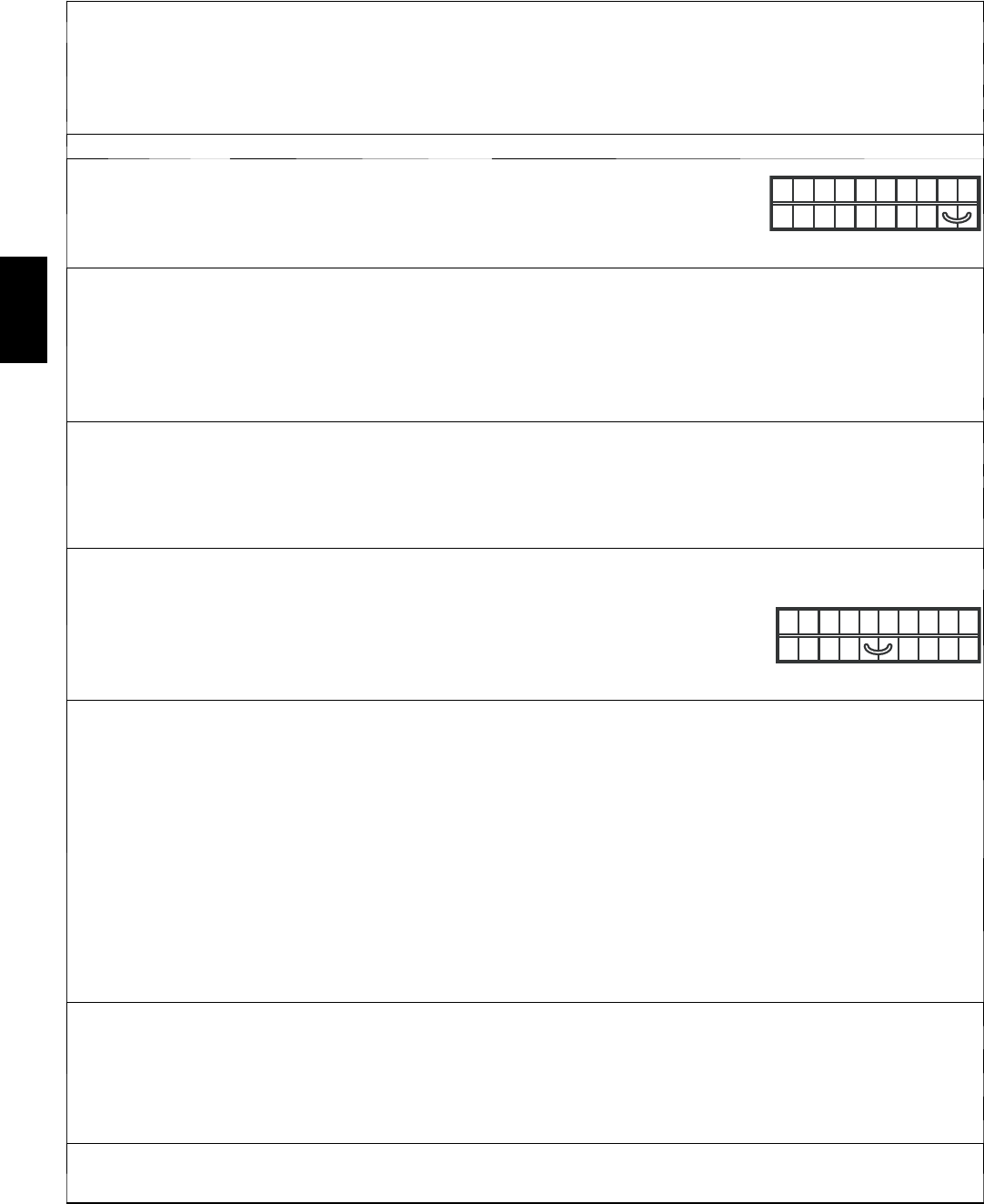
S Jump th e OL and OC terminals. If the unit
switc h to hig h s pee d, re mov e th e
dehumidistat or push button and test it right
beside the unit using anothershorter wire.If
it works here, change the wire. If it doesn’t,
change the dehumidistat or the push button.
NO C NC I OC OL Y R G B
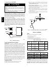
5. The supply and/or
exhaust motor do not
work.
S The circuit board may be defective. S Press on the integrated control push button until the unit turn on low speed (the
LED will light AMBER). U sing a multimeter, check the voltage on J4--1 and
J4--2 (for sup ply motor), and on J5--1 and J5--2 (for exh aust motor). The reading
must be ± 68VAC. Then set the unit on high speed by pressing on the integrated
control 1 more time ( the LED will light GREEN).Using a multimeter, check the
voltage on J4--1 and J4--2 (for supply motor), and on J5--1 and J5 --2 (for exhaust
motor). The reading must be ±120VAC.If allthe readings correspond to the right
voltage values, the circuit board is not defective. If one or both readings are
different, change the circuit board.
S The motor(s) may be defective. S Using a multimeter, check the ohms value on each motor connectors. Black
motors values: For BLUE and BLACK motor wires, the right v alue is ± 55ohms.
For BLUE and BROWN motor wires, the right value is ± 35 ohms. For BROWN
and BLACKmotor wires,the rightvalue is ±89 ohms. Aluminum motors values:
For BLUE and BLACK motor wires, the right value is ±51 ohms.For BLUEand
BROWN motor wires, the right value is ± 47 ohms. For BROWN and BLACK
motor wires, the right value is ± 98 ohms. If he ohms values are the same, the
motor is not defective. Replace the motor capacitor.
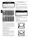
6. The defrost cycle
does not work (the
fresh air duct is fro-
zen OR the fresh air
distributed is very
cold. (See Table 7 for
Defrost Cycle Tim-
ing.)
S Ice deposits may be hindering the
damper operation.
S Remove the ice.
S The damper rod or the port damper itself
may be broken.
S Inspect these parts and replace if necessary.
S The damper actuator or circuit board
may be defective.
S See Problem 2.
7. The integrated con-
trol push button does
not work.
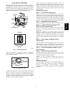
S The 30 --second boot sequence is not
completed.
S See Boot Sequence.
ERV / HRV