


12
M1
T1
R1
Field wiring
remote control
(see notes 3, 4)
120V, 60Hz
W1
F1
J5
J7
J6
J4
ELECTRONIC ASSEMBLY
1
2
3
1
2
1
2
1
2
3
1234
12
12345
12345
J8
J9
J11
J10
12
J12
J13
J14
10
9
8
7
6
5
4
3
2
1
YEL
RED
GRN
BLK
M2
C1
C2
BLK
BLU
BRN
BLK
BLK
BLK
BLK
BLK
BLU
BRN
24V class 2
9.5V
class 2
BLK
WHT
BRN
BRN
Y
Y
GRN
See note 1
120V
90V
68V
neutral
BLK
BLU
RED
WHT
Door interlock
switch
(magnetically
actuated reed
switch)
WHT WHT
Exhaust fan motor
Exhaust fan motor
capacitor
Supply fan motor
capacitor
Supply fan motor
GRN
GRN
1234512
12
J3
J2
J1
t
o
M3
Damper motor
BLK
BLK
Override switch
(optional; see notes
3, 4)
Furnace blower interlock
J14-1 : NO Connect to R at Furnace / Fan Coil
J14-2 : COM Connect to G at Furnace / Fan Coil
J14-3 : NC Connect to G at Thermostat
(see notes 3 , 5)
A2
DAMPER ELECTRONIC
ASSEMBLY
Defrost temperature
sensor
S1
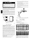
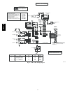
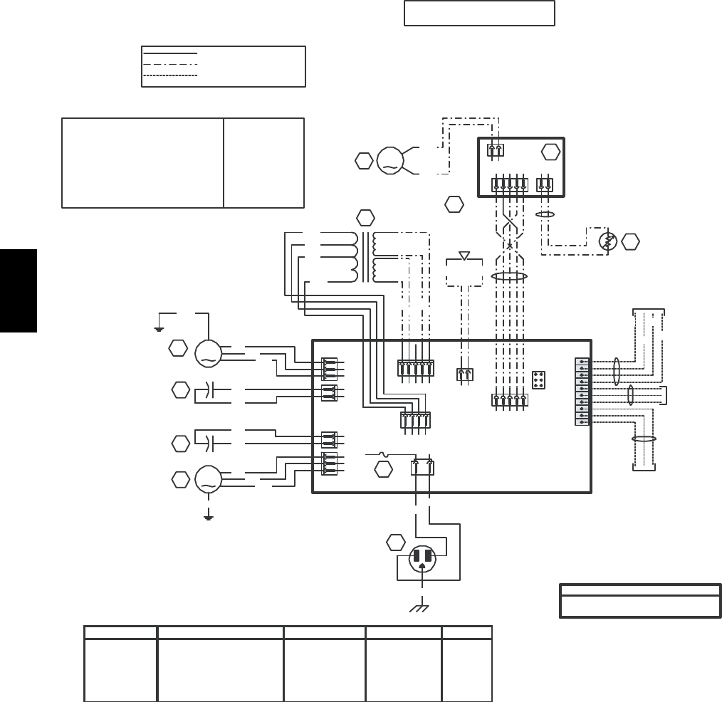
ICP
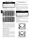
CONNECTION DIAGRAM
Line voltage factory wiring
Class 2 low voltage factory wiring
Class 2 low voltage field wiring
COLOR CODE
BLK BLACK
BLU BLUE
BRN BROWN
GRN GREEN
GRY GRY
ORG ORANGE
RED RED
WHT WHITE
YEL YELLOW
1. For continued fire protection, use specified UL
listed/CSA Certified line fuse.
2. If any of the original wire, as supplied, must be
replaced,
use the same equivalent wire.
3. Field wiring must comply with applicable codes,
ordinances and regulations.
4. Remote controls available. See instruction
manual. (class
2 circuit)
5. Furnace fan circuit must be class 2 circuit only.
MODELS
HRVCCSHA1100, HRVCCSVA1100,
ERVCCSHA1100, ERVCCSVA1100,
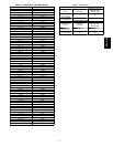
K5 K2 K3 K1 MODE M1 "Supply" M2 - "Exhaust" DAMPER
0 0 0 0 OFF OFF OFF Closed
1 0 1 1 Exchange low speed LO LO Opened
1 1 1 1 Exchange high speed HI HI Opened
1 1 1 0 Circulation high speed HI OFF Closed
1 1 1 0 Defrost HI OFF Closed
A07118
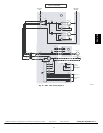
Fig. 17 -- ERV / HRV Wiring Diagram
ERV / HRV