


4
Connect Ducts to ERV/HRV
PROPERTY DAMAGE HAZARD
Failure to follow this caution may result in minor property
damage from sweating duct or loss of unit efficiency and
capacity.
If ERV/HRV duct work is installed in an unconditioned
space, insulated flexible duct is required.
CAUTION
!
Insulated flexible duct is required on both fresh--air inlet and
exhaust--air outlet ducts connecting to exterior wall. When
using insulated flexible duct, the vapor barrier of the flexible ducts
must be taped very tight to prevent condensation problems. To
reduce pressure drop, stretch the flex duct and support it in a proper
manner to avoid reduced airflow.
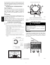
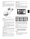
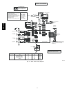
When connecting the ERV/HRV to a return--air duct system,
insulated flexible duct can be used. However, when metal or rigid
ducts are applied use approximately 18” (457mm) of flexible duct
at ERV/HRV ports for fresh--air supply, and stale--air return. When
using metal duct from fresh--air supply to system duct work, the
metal duct should be insulated. (See Fig. 8.) This can act as a
silencer when connecting ducts to return--air duct s ystem. This
should eliminate transmission of noise or vibration from unit to
main duct system.
FRESH-AIR
SUPPLY
STALE-AIR
RETURN
FLEXIBLE DUCTS CONNECTING TO
RETURN-AIR DUCT SYSTEM
A08102
Fig. 8 -- Flexible Duct Fit--Up
Locate and Install Exterior Hoods
IMPORTANT: To prevent condensation problems, insulated
flexible ducts are required on both fresh-- air inlet and exhaust--air
outlet ducts connecting between ERV/HRV and exterior w all.
Fresh--air intake and stale--air exhaust must be separated by at least
6 ft (1.8m). Fresh--air intake must be positioned at least 10 ft (3m)
from nearest dryer vent, furnace exhaust, driveway , gas meter, or
oil fill pipe. Fresh-- air intake must be positioned as far as possible
from garbage containers and potential chemical fumes. When
possible, it is advised to locate the intake and exhaust hoods on
same side of house or building. The intake and exhaust hoods
should never be located on interior corners or in dead air pockets
(See Fig. 7). Both intake and exhaust hoods must be 18” (457mm)
from ground and at least 12” (305mm) above anticipated snow
level.
After selecting proper hood locations, make appropriate size hole
through exterior wall, pass flexible duct through hole and insert
hood tube into duct. Tape duct vapor barrier tightly around hood
tube and insert assembly back into wall and f asten securely.
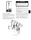
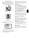
Condensate Drain
(For ERV, skip this step and continue to the next step.)
To connect condensate drain, proceed as follows:
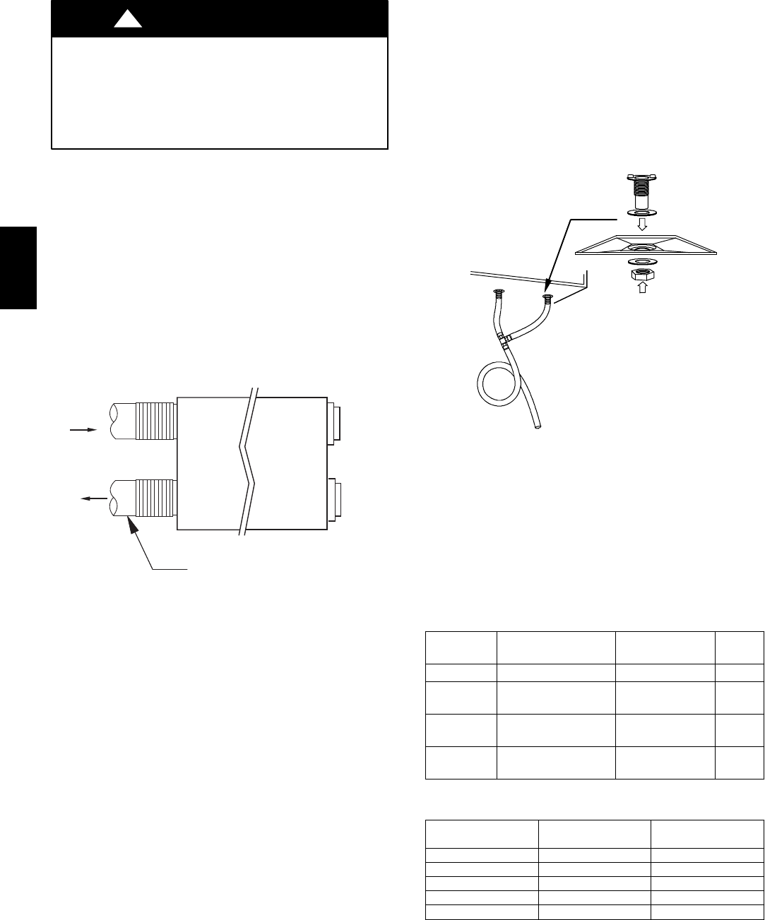
1. Punch out holes in foam insulation and door, then insert
sleeved grommets into bottom of unit using the gasket
washer and nut. (See Fig. 9.)
2. Cut two sections of plastic tubing, about 12” / 305mm long
and a ttach them to each drain.
3. Join the two short sections of plastic tubing to the “T” con-
nector and the main tube as shown.
4. Make a loop in the tubing below the “T” connector to create
a trap to prevent sewer gases from entering the ventilation
system. (See Fig. 9.)
5. Connect unit drain to building’s main drain. Provide slight
slope from unit for run-- off.
A99268
Fig. 9 -- Condensate Drain With Loop Trap (HRV Only)
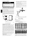
WALL CONTROL
Types
Four remote wall control options are available:
1. Basic Control (see Table 1).
2. OneTouch Control
3. Standard Control (includes dehumidistat)
4. Latent Control (includes humidistat for use with ERV’s only)
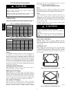
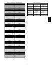
Table 1 – Basic Control
MODE OPERATION
DAMPER
POSITION
FAN
SPEED
Off Off Closed to outside Off
Low
Air exchange with
outside
Open to outside Low
Intermittent
Air exchange with
outside
Open to outside Low
High
Air exchange with
outside
Open to outside High
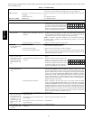
Table 2 – Recommended Humidity Levels
OUTSIDE
TEMPERATURE
DO UBL E --- PA NE
WINDOWS
T RI PL E --- PA NE
WINDOWS
50°F/10°C 55% 65%
32°F/0°C 45% 55%
14°F / --- 1 0°C 35% 45%
--- 4°F / --- 2 0°C 30% 45%
--- 22°F / --- 30 °C 25% 35%
Location
The Standard Control and the Latent Control sense humidity and
not temperature. They must be located in an area where they will
continually monitor fresh air circulating within the home. Install
ERV/HRV wall controls as close as possible to main system
ERV / HRV