


6
DEHUM -- will only turn on if humidity is 3% over setpoint.
The speed is determined by indoor humidity and outdoor
temperature.
Cooling:
AUTO -- the ventilator selects the speed based on i ndoor
humidity and outdoor temperature. It may cycle on/off every
30 minutes depending on humidity and outside temperature.
LOW -- l ow speed all of the time.
HIGH -- high speed all of the time.
If the fan speed is set to Auto and the ventilator wants to run, the
fan speed will run at High continuous speed. Otherwise, the fan
will stay at the chosen continuous fan speed.
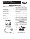
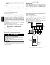
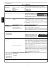
BOOT SEQUENCE
The unit boot sequence is similar to a personal computer boot
sequence. Each time the unit is plugged after being unplugged, or
after a power failure, the unit will perform a 30--second booting
sequence before starting to operate. During the booting sequence,
the integrated control LED will light GREEN or AMBER for 5
seconds, and then will shut off for 2 seconds. After that, the LED
will light RED for the rest of the booting sequence. During this
RED light phase, the unit is checking and resetting the motorized
damper position.
Once the motorized damper position completely set, the RED light
turns off and the booting sequence is done.
NOTE: No command will be taken until the unit is fully booted.
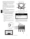
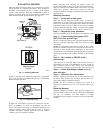
ELECTRICAL CONNECTIONS
115--V AC Wiring
The ERV/HRV operates on 115VAC. It comes with a power cord
attached to unit and ready to plug into a fused outlet. Unit must be
grounded for proper operation.
All electrical connections must comply with National and Local
Electrical Codes, or other ordinances that might apply.
ELECTRICAL SHOCK / FIRE HAZARD
Failure to follow this warning could result in personal injury,
death and/or property damage.
Do not use an extension cord as a power source for operating
the ERV/HRV.
!
WARNING
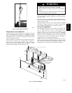
12VDC Wiring
The ERV/HRV circuit board, wall control, and accessories operate
on 12VDC. See Wall Control section, item Wiring and Fig. 5 and
10 for more information.
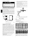
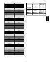
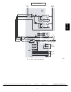
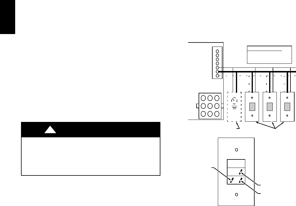
ACCESSORIES
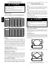
20 Minute Timer
A push button timer can be used to override the wall control and
put the ERV/HRV into high speed for 20 minutes. Connect
switches in parallel and connect leads to ERV/HRV terminals I,
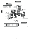
OC, and OL (See Fig. 12). Push button locations are ideal in
special activity areas, such as, bathroom, or kitchen, where
high--speed exhaust operation is needed for a short period of time.
NOTE: The 20 minute timer will not function properly unless
ERV/HRV wall control is applied and working correctly. Timing
function is internal to electronic circuit board, it is activated by a
momentary contact between OC and OL. The I connection is to
illuminate the push button. The maximum number of push button
timers that can be applied is 5.
60 Minute Adjustable Timer
A 60 minute adjustable timer can also be used to override wall
control and put HRV into high-- speed operation for a select amount
of time. Connect timer in parallel with push button timers, or to
ERV/HRV terminals OC and OL. (See Fig. 12.)
The 60 minute timer will provide a minimum of 10 minutes, and a
maximum of 60 minutes of ventilation at high speed.
3
4
5
I
OC
OL
YELLOW
BLACK
RED
ELECTRONICCONTROL
BOARD
BACKOF PUSHBUTTONSWITCH
J3
J1
6
7
8
9
41 7
52 8
63 9
BLACK– ( J 3 -4)
COMMON
TERMINAL
STRIP
YELLOW –(J3-3)
INDICATOR
TERMINAL STRIP
RED –(J3-5)
SWITCH
TERMINAL STRIP
BLACK– COMMON, (J3--4)
YELLOW –INDICATOR, (J3--3)
THE WIRES FROM THE SWITCH
RED– SWITCH, (J3--5)
(OC)
(I)
(OL)
(OPTIONAL)
60 MINUTE TIMER
(OPTIONAL)
PUSH BUTTON SWITCHES
(5 SWITCHES MAXIMUM)
A98386
Fig. 12 -- Push Button Timer Wiring Layout
ERV / HRV