


2
The model operates at 2 airflows, 50 CFM in low speed and 100
CFM in high speed. This unit comes in two configurations, vertical
or horizontal. Special attention should be given to duct application,
balancing the ERV/HR V, and locating unit for easy access a nd
routine maintenance.
INSTALLATION CONSIDERATIONS
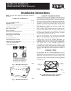
Inspect Equipment
Move carton to final installation location. Remove ERV/HRV from
carton taking care not to damage unit. Remove all packaging and
inspect unit for damage. Remove parts bag from inside unit. File
claim with shipping company if shipment is damaged or
incomplete. Check to make sure ERV/HRV unit matches Fig. 1 or
Fig. 2.
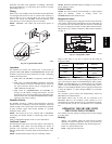
Select Location
The ERV/HRV should be located in a conditioned space and in
close proximity to a fused power source. It should be easily
accessible for routine maintenance.
If ERV/HRV is installed independent of a forced--air system, unit
should be located near the center of the air distribution system. If
ERV/HRV is installed in conjunction with a forced--air system, unit
should be located next to (or close to) the indoor equipment.
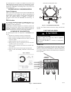
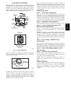
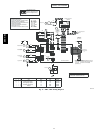
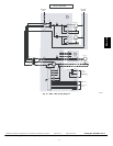
COMPONENT DESCRIPTION
The following listed items are components of ERVBBSHA (See
Fig. 4).
1. Exhaust --air connected to outdoor air exhaust hood.
2. Fresh --air intake connected to outdoor air inlet hood.
3. Fresh --air supply from ERV connected to return--air duct o f
forced--air system.
4. Mechanical filters trap dust contained in t he air.
5. Energy recovery core is a cross--flow type. The core trans-
fers heat be tween the 2 air streams.
6. Blowers bring in fresh--air from outside and exhaust stale--
air to outside.
7. Electronic control circuit ensures proper unit operation.
8. Stale air return from building connected to return--air duct
system.
ERV ports on side (bottom view)
3
2
8
1
4
4 5
6
7
A05263
Fig. 4 -- Conventional Horizontal Unit
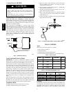
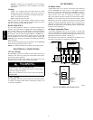
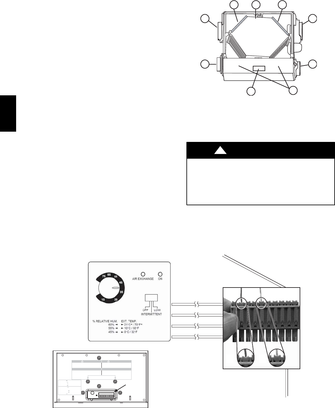
See Fig. 5 for terminal connector block for wiring wall and timer
controls.
UNIT INSTALLATION
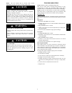
UNIT DAMAGE HAZARD
Failure to follow this caution may result in equipment
damage or improper operation.
Do not install ERV/HRV in a corrosive or contaminated
atmosphere.
CAUTION
!
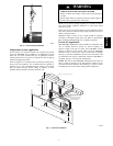
Mount Unit
The ERV/HRV can be suspended from floor joists using chains and
4 springs. Attach metal hanging bracket to all 4 sides of cabinet.
(See Fig. 6.) The unit may be installed on a shelf if an isolation pad
is provided to dampen vibration. Unit should always be installed as
level as possible.
CONTROL
CONNECTOR
WALL CONTROL
YELLOW
RED
GREEN
BLACK
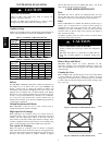
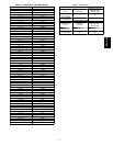
W ARNING
Ri s k of electric s hoc k. Befo re perfo rmin g
any maintenance or s ervicin g, al way s
dis connect the unit fr om it s p ow er s our ce .
AVERTI SS EMENT
Da nger d’électr ocution. Dé branchez
toujours l’a ppareil av ant d’entrep rendr e
des tra vaux d’entretien ou de ré paration.
CA UTION
Un scr ew boths cr ews to op en the electrical
com par tment . To com plete ly remo ve , detac h
fr om it s retention wire in s ide.
AT TENTION
Dé vi sser les deux vis pour ouvrir le com p ar timent
électrique . Pour retirer com plètement , le
détacher de son fil de rétention intérieur .
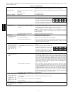
No light OFF or remote controled
Amber light LOW speed
Green ligh HIGH speed
Blinking light See User Manual
Sans lumière Arrêté ou contrôlé
par contrôle mura l
Lumière ambre Basse vitesse
Lumière verte Haute vitesse
Clignotant Vo ir guide d’utilisation
Terminal
Connector
A
B
A07418
Fig. 5 -- Control Connector
ERV / HRV