


17
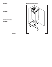
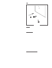
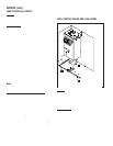
FIG. 7 THERMOSTAT TERMINALS
P1448
BLK from Limit
Thermostat
BLK from Tank
Heater Switch
10. Carefully bend the capillary tube so that the tube
and bulb inside the tank are in the vertical position
and away from any electrical connections.
SERVICE (cont.)
CONTROL THERMOSTAT (cont.)
11. Refer to Fig. 7 and reconnect the wires.
NOTE - The capillary tube must be clear of any electri-
cal termination and not kinked.
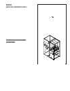
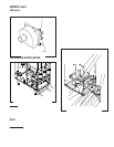
MECHANICAL THERMOSTAT
TAN to WHI/BRN
on Tank Heater Switch
BLK to Main
Wiring Harness
WHI to Main
Wiring Harness
BLK to Limit
Thermastat
ELECTRONIC THERMOSTAT
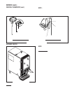
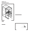
DISPENSE SWITCH
P1436
Location:
The dispense switches are located on the lower
outside of the dispenser door.
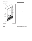
FIG.8 DISPENSE SWITCH
H
O
T
L
I
Q
U
I
D
R
E
L
E
A
S
E
B
U
T
T
O
N
W
H
E
N
C
U
P
IS
2
/3
F
U
L
L
P
L
A
C
E
C
U
P
H
E
R
E
P
L
A
C
E
C
U
P
H
E
R
E
P
L
A
C
E
C
U
P
H
E
R
E
! W
ARNING
P
US
H and HO
LD BU
TTO
N UNTIL CU
P
IS 2/3 FULL, THE
N R
ELEA
SE
NOTE: The center dispense switch is for FMD-3 Mod-
els only.
Test Procedure:
1. Disconnect the dispenser from the power source.
2. Open the dispenser door and remove the bottom
door cover.
3. Disconnect the wires from the door interconnect
wiring harness to the dispense switch to be
tested.
4. Check for voltage across the black and red/black
wires for the right dispense switch, black and
red/white wires for the center dispense switch or
the black and red wires for the left dispense
switch from the door interconnect wiring har-
ness. Connect the dispenser to the power supply.
The indication must be:
a) 120 volts ac for two wire 120 volt models.
b) 120 volts ac for three wire 120/208 volt or 120/
240 volt models.
c) 240 volts ac for two wire 240 volt models.
5. Disconnect the dispenser from the power source.
If voltage is present as described, proceed to #6.
If voltage is not present as described, refer to the wir-
ing diagram and check the dispenser wiring harness.
28364 071598