


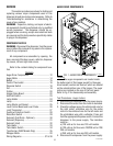
12
SERVICE
This section provides procedures for testing and
replacing various major components used in this
dispenser should service become necessary. Refer to
Troubleshooting
for assistance in determining the
cause of any problem.
WARNING - Inspection, testing, and repair of electri-
cal equipment should be performed only by qualified
service personnel. The dispenser should be un-
plugged when servicing, except when electrical tests
are required and the test procedure specifically states
to plug-in the dispenser.
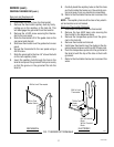
COMPONENT ACCESS
WARNING - Disconnect the dispenser from the power
source before the removal of any panel or the replace-
ment of any component.
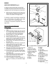
All components are accessible by opening the
door, removal of the door covers, reflector, dispenser
top covers, left and right side covers.
Refer to the contents listing for component loca-
tion.
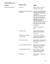
Contents
Auger Drive Components......................................12
Auger Motor .........................................................14
Ballast ...................................................................15
Control Thermostat...............................................16
Dispense Switch ...................................................18
Fan........................................................................19
Frother ................................................................. 20
Hopper Delay Board..............................................22
Hot/Cold Switch ....................................................23
Lamp Holder .........................................................24
Lamp ....................................................................24
Lamp Starter and Socket ......................................25
Level Control Board and Level Probe ....................26
Limit Thermostat ..................................................27
Overflow Protection Switch ..................................28
Rinse/Run Switch .................................................29
Solenoid (Cold Drink - Optional) ...........................30
Solenoid (Dispense) .............................................31
Solenoid (Inlet) .....................................................32
Tank Heater ..........................................................33
Tank Heater Switch ...............................................34
Transformer (240V Models Only) .........................35
Whipper Motor .....................................................20
Wiring Diagrams.......................................... 37 & 38
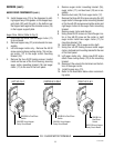
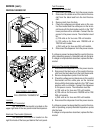
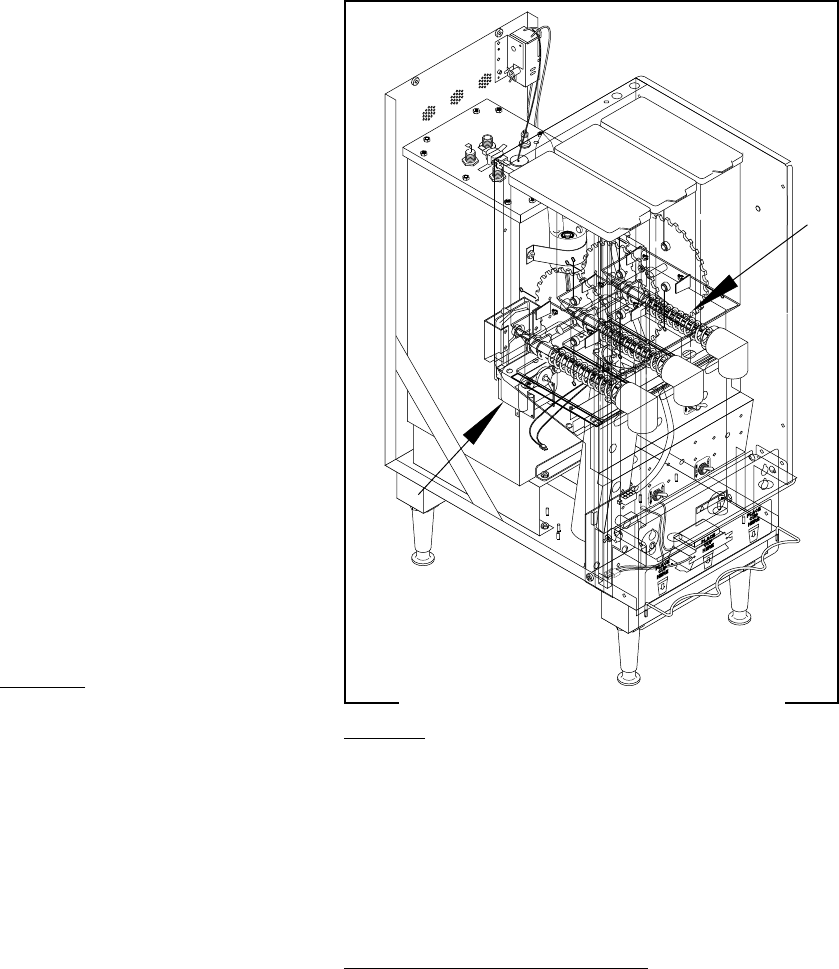
FIG. 1 AUGER DRIVE COMPONENTS
Location
The auger components are located inside
the bottom part of the hopper except for the auger
drive bracket, washer and locknut, which are located
on the outside bottom rear of the hopper. The auger
motors are located on the rear of the front panel.
Refer to Fig. 2 for disassembly and assembly.
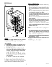
Test Procedures - Auger motors
1. Disconnect the dispenser from the power source.
2. Disconnect the wires from the motor to be tested.
3. Check the voltage across the white/violet wire for
the right motor, white/blue wire for the center
motor or the white/red wire for the left motor and
the white/black wire with a voltmeter. Press and
hold the appropriate Dispense switch. Connect the
dispenser to the power supply. The indication
must be :
a) 120 volts ac for two wire 120 volt models.
b) 120 volts ac for three wire 120/208 volt or 120/
240 volt models.
c) 240 volts ac for two wire 240 volt models.
4. Disconnect the dispenser from the power supply.
P1199.45
AUGER DRIVE COMPONENTS
27591 031597