


48
+
A
C
A
C
SERVICE (CONT.)
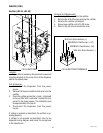
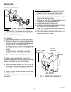
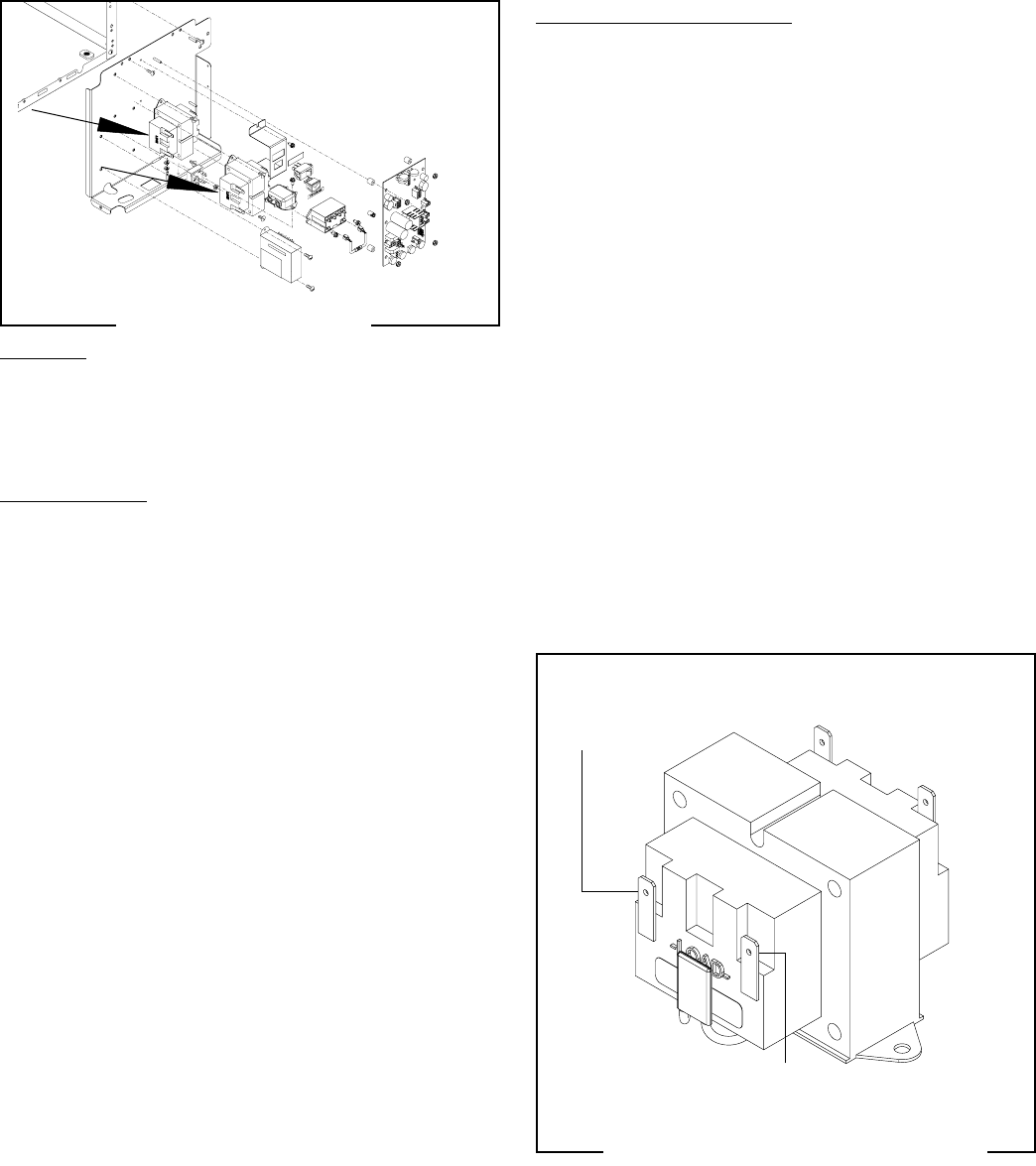
Transformer (all Models)
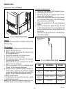
Removal and Replacement:
1. Loosen the two #8-32 screws securing the com-
ponent bracket to the dispenser housing base.
2. Pull component bracket out the front of the dispenser
far enough so the transformer can be disconnected
from the main wiring harness.
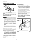
3 Remove the two #6-32 keps nuts securing the
transformer to the component bracket.
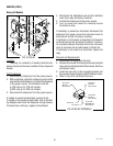
5. Remove and discard the transformer.
6. Install new transformer on the component bracket
and secure with two #6-32 keps nuts.
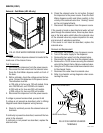
7. Refer to Fig. 70 and connect the transformer to the
main wiring harness.
8. Place the component bracket into position and
tighten the two #8-32 screws.
BLU to Control
Board J6-3,J12-3
WHI/BLU to Control
Board J6-1,J12-1
WHI from
Power Cord
BLK from
Power Cord
FIG. 70 TRANSFORMER TERMINALS
P1647
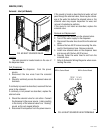
FIG. 69 TRANSFORMER
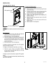
Location:
The transformer is located on the electrical com-
ponent mounting bracket on the lower front of the
dispenser behind the splash panel.
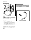
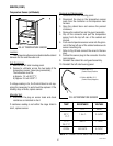
Test Procedure:
1. Disconnect the dispenser from the power source.
2. Check the voltage across black wire and the white
wire from the main harness. Connect the dispenser
to power source. The indication must be:
a) 120 volts ac for two wire 120 volt models, three
wire 120/208 volt and three wire 120/240 volt
models.
b) 240 volts ac for two wire 240 volt models.
c) 230 volts ac for two wire 230 volt models.
4. Disconnect the dispenser from the power source.
If voltage is present as described, proceed to #5.
If voltage is not present as described, refer to the Wiring
Diagrams and check the main wiring harness.
5. Check the voltage between J6-1 and J6-3 at the
control board. Connect the dispenser to the power
source. The indication must be 24 volts ac.
If voltage is present as described the transformer is
operating properly.
If voltage is not present as described, replace the
transformer.
P3864
49179 110613