


25
SERVICE (CONT.)
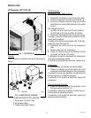
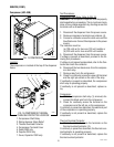
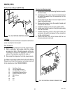
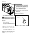
Control Board, Main (all Models)
FIG. 23 CONTROL BOARD
P3250.25
Location:
The Main Control Board is located on the electrical
component enclosure behind the splash panel.
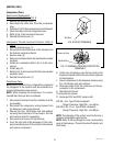
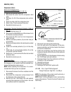
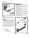
Test Procedure:
Power Supply Circuitry:
1. Disconnect the dispenser from the power source.
2. With a voltmeter, back probe check the voltage
across pins 1 & 3 of the J6 connector on the wir-
ing harness. Connect the dispenser to the power
source. The indication must be 24 volts ac.
3. Disconnect the dispenser from the power source.
If voltage is present as described, proceed to step 4.
If voltage is not present as described, refer to the Wiring
Diagrams and check the dispenser wiring harness back
to the transformer (See TRANSFORMER).
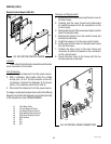
4. Disconnect the dispenser from the power source.
5. With a voltmeter, back probe check the voltage
across pins 1 & 3 of the J12 connector on the
wiring harness. Connect the dispenser to the power
source. The indication must be 24 volts ac.
6. Disconnect the dispenser from the power source.
If voltage is not present as described, refer to the Wiring
Diagrams and check the dispenser wiring harness back
to the transformer (See TRANSFORMER).
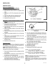
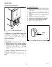
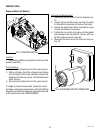
Removal and Replacement:
1. Remove the four #6-32 screws securing the control
board to the component bracket.
2. Disconnect all the plugs on the main wiring harness
from the connectors on the control board.
3. Remove the spacers from the control board and
discard.
4. Install the spacers on to the new control board
5. Reconnect all plugs on the main harness to the
connectors on the control board.
6. Install new control board on the component bracket
using four #6-32 screws.
NOTE: Verify all ground wires are connected to the
grounding stud and secured with nuts.
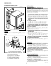
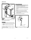
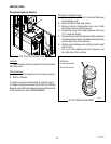
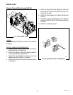
FIG. 24 CONTROL BOARD CONNECTORS
JDF-4S shown
JDF-2S
JDF-4S
49179 110613