


34
SERVICE (CONT.)
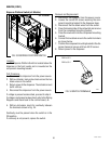
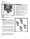
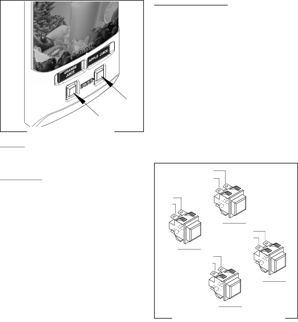
Dispense Switches (JDF-2S, JDF-4S)
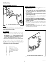
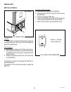
FIG. 41 DISPENSE SWITCHES
P1449
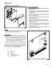
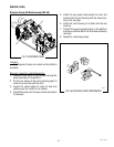
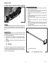
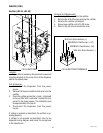
FIG. 42 DISPENSE SWITCH TERMINALS
Station #1
Station #2
Station #3
BLK
RED
BLK
GRN
Location:
The dispense switches are located on the lower
outside of the dispenser door.
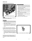
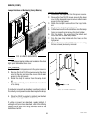
Test Procedure:
1. Disconnect the dispenser from the power source.
2. Remove the five screws attaching the dispenser
door cover to the door and move the door cover
to gain access to the switches.
3. With a voltmeter, check the voltage across the two
wires for each dispense switch. Connect the dis-
penser to the power source. The indication must
be +5 volts dc.
If voltage is present as described, proceed to #4.
If voltage is not present as described, refer to the Wiring
Diagrams and check the dispenser wiring harness.
4. Check for continuity across the terminals (top right
to top left) of the dispense switch with the switch in
the “ON” position. Continuity must not be present
when the switch is in the “OFF” (released) posi-
tion.
If continuity is present as described, reconnect the door
wiring harness, the switch is operating properly.
If continuity is not present as described, replace the
switch.
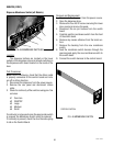
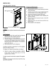
Removal and Replacement:
1. Disconnect the dispenser from the power source.
2. Remove the five screws attaching the dispenser
door cover to the door and move the door cover
to gain access to the switches.
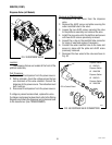
3. Disconnect the wires on the dispense switch to be
removed from the door wiring harness.
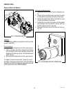
4. Compress the clips inside the door on the dispense
switch and gently push the switch through the
opening.
5. Push new switch into the opening and spread the
clips to hold the switch in the door.
6. Reconnect the wires to the dispense switch from
door wiring harness.
7. Reinstall the door cover and secure with the five
screws previously removed.
8. Refer to Fig. 42 when reinstalling wires.
Station #4
BLK
ORN
BLK
YEL
49179 110613