


12
SERVICE
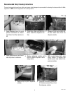
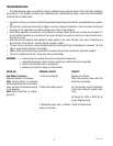
This section provides procedures for testing and replacing various major components used in this dispenser
should service become necessary. Refer to Troubleshooting for assistance in determining the cause of any
problem.
WARNING - Inspection, testing, and repair of electrical equipment should be performed only by qualified service
personnel. The dispenser should be disconnected from the power source when servicing, except when electrical
tests are required and the test procedure specifically states to connect the dispenser to the power source.
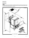
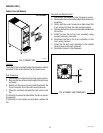
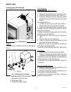
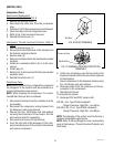
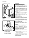
COMPONENT ACCESS
WARNING - Disconnect the dispenser from the power source before the removal of any panel or the replacement
of any component.
All components are accessible by opening the door, removal of the door panels, dispenser top covers,
hopper(s), hopper support plate, splash guard, splash panel w/drip tray, lower front access panel and rear ac-
cess cover.
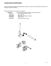
Refer to the contents listing for component location.
INDEX
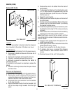
Access Panels ..................................................................................................................................13
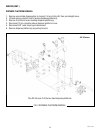
Dispense Platform Removal .............................................................................................................14
Ballast ..............................................................................................................................................15
Cabinet Fan ......................................................................................................................................16
Compressor .....................................................................................................................................17
Compressor Switch ..........................................................................................................................23
Condenser Fan .................................................................................................................................24
Control Board (Main) .......................................................................................................................25
Control Board (Portion Control Models) ..........................................................................................26
Circulation Pump .............................................................................................................................29
Dispense Platform Switch ................................................................................................................ 30
Dispense Pump ................................................................................................................................31
Dispense Motor ................................................................................................................................32
Dispense Valve ................................................................................................................................. 33
Dispense Switches ........................................................................................................................... 34
Cold Water Dispense Switch ............................................................................................................35
Dispense Membrane Switches .........................................................................................................36
Cold Water Membrane Switch ..........................................................................................................37
EMI Filter ..........................................................................................................................................38
Lamp ................................................................................................................................................39
Lamp Holder ....................................................................................................................................39
LED Lamp ........................................................................................................................................40
Rectifier ...........................................................................................................................................41
Relay ................................................................................................................................................ 42
Resistor ...........................................................................................................................................43
Solenoid (Cold Water) ...................................................................................................................... 44
Solenoid (Inlet) ................................................................................................................................45
Temperature Probe...........................................................................................................................46
Temperature Sensor ......................................................................................................................... 47
Transformer .....................................................................................................................................48
Transformer-Lited Doors ..................................................................................................................49
Circuit Board Triac Map ....................................................................................................................50
Schematic Wiring Diagrams .............................................................................................................51
49179 012214