


47
SERVICE (CONT.)
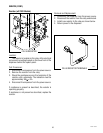
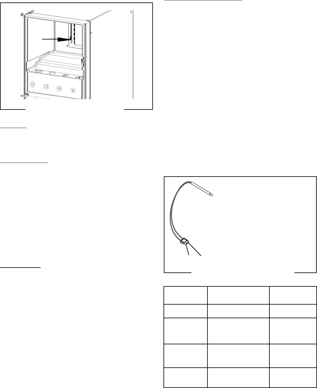
Temperature Sensor (all Models)
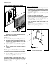
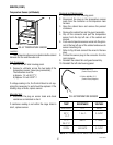
FIG. 68 TEMPERATURE SENSOR
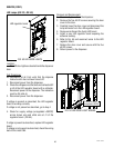
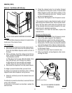
FIG. 67 TEMPERATURE SENSOR
Location:
The Temperature Sensor is located inside the cabinet
between the fan and the water coil.
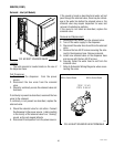
Test Procedures:
1. Remove the left side housing panel.
2. Connect a voltmeter across the two leads of the
temperature sensor (leave plug connected);
The indication must be:
a) Approx. 1.4 vdc @ 71° F
b) Approx. 2.6 vdc @ 32° F
If voltage reading is 0v, the Control Board is not sup-
plying the necessary 5v and should be replaced. If the
reading stays at 5vdc, replace sensor.
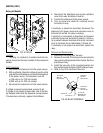
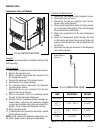
Alternate Test:
2. Disconnect the plug on sensor leads and check
resistance as indicated in chart.
If resistance reading is not within the range listed in
chart, replace sensor.
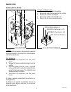
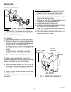
Removal and Replacement:
1. Remove the left side housing panel.
2. Disconnect the plug on the temperature sensor
leads from the connector on the dispenser main
harness.
3. Open the cabinet door and remove the product
containers.
4. Remove the cabinet fan and fan guard assembly.
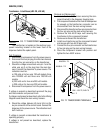
5. Clip off the connector and pull the temperature
sensor from the top left rear of the cabinet and
discard.
6. Push new temperature sensor wires into the grom-
met at the top left rear of the cabinet and secure to
sensor mounting clip.
7. Refer to Fig. 68 and connect the wires to the new
plug.
8. Connect the sensor plug to the connector from the
main harness.
9. Reinstall the cabinet fan and guard assembly.
10. Reinstall the left side housing panel.
1. BLK to GRY J7-1
(Control Board) Positive
2. BLK to WHI/BLK J7-2
(Control Board) Negative
2 1
TEMP RESISTANCE VOLTAGE
SHORTED 0 Ω 0VDC
32° F 1.5k Ω 2.5VDC
0° C
77° F 350 Ω 1.1VDC
25.0° C
OPEN INFINITE 5.0VDC
NOTE: ALL FIGURES LISTED ABOVE ARE APPROXIMATE.
49179 020514