


Page 13
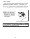
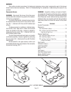
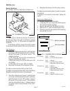
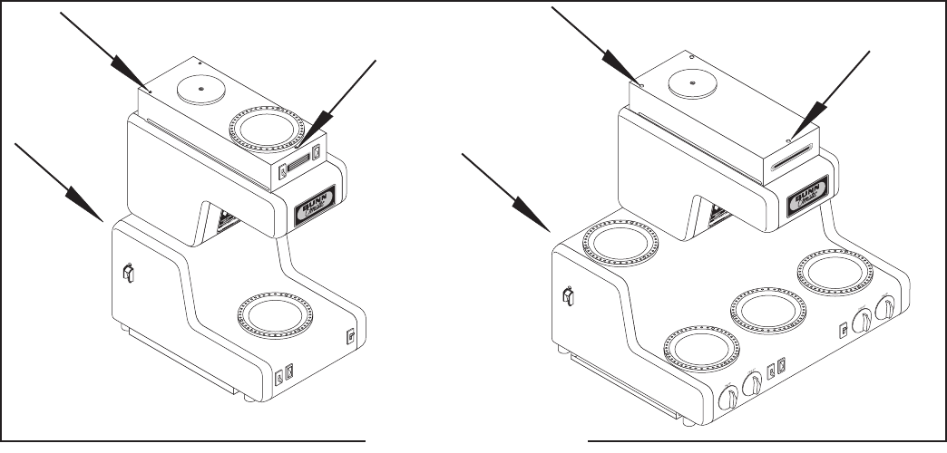
FIG. 1 ACCESS PANELS
SERVICE
This section provides procedures for testing and replacing various major components used in this brewer
should service become necessary. Refer to Troubleshooting for assistance in determining the cause of any
problem.
Component Access
WARNING - Disconnect the brewer from the power
source before the removal of any panel or the replace-
ment of any component.
The control thermostat, solenoid valve and relay
are located under the top cover or top warmer hous-
ing, FIG. 1, attached with three #8-32 slotted-head
screws.
The base warmer(s), switch(es), indicator lamp,
start switch, tank “keep warm” heater and terminal
block are located in the base. Access is gained by
removing the rear panel, FIG. 1 attached with two
#8-32 slotted-head screws
The limit thermostat and tank heater are located
on the tank assembly. Access is gained by removing
the rear panel, FIG. 1 attached with two #8-32 slotted
head screws.
On the model OL, the upper warmer, switch, and
associated indicator lamp are located on the removable
top warmer housing, FIG. 1.
WARNING - Inspection, testing, and repair of electri-
cal equipment should be performed only by qualified
service personnel. The brewer should be disconnected
from the power source when servicing, except when
electrical tests are required and the test procedure
specifically states to connect the brewer to the power
source.
Contents
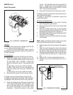
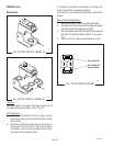
Control Thermostat ............................................... 13
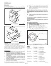
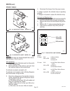
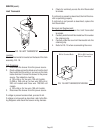
Warmer(s)
OL: Brew Station & Upper ..............................................14
RL: Left Rear, Left Front, Brew Station,
Right Rear & Right Front ............................................ 14
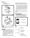
Warmer Switch(es)
OL: On/Off Brew Station & Upper ...................................15
RL: On/Off Brew Station .................................................15
RL: Left Rear, Left Front, Right Rear
& Right Front Rotary ..................................................16
Start Switch .......................................................... 17
Indicator Lamp(s) ................................................. 18
Limit Thermostat ................................................... 19
Solenoid Valve ......................................................20
Relay .................................................................... 21
Tank Heater ...........................................................22
Over Flow Safety Switch ....................................... 23
Master ON/OFF Switch .......................................... 24
Wiring Schematics .............................................. 25
P1712
P1713
32430 010308