


Page 22
SERVICE (cont.)
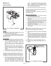
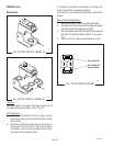
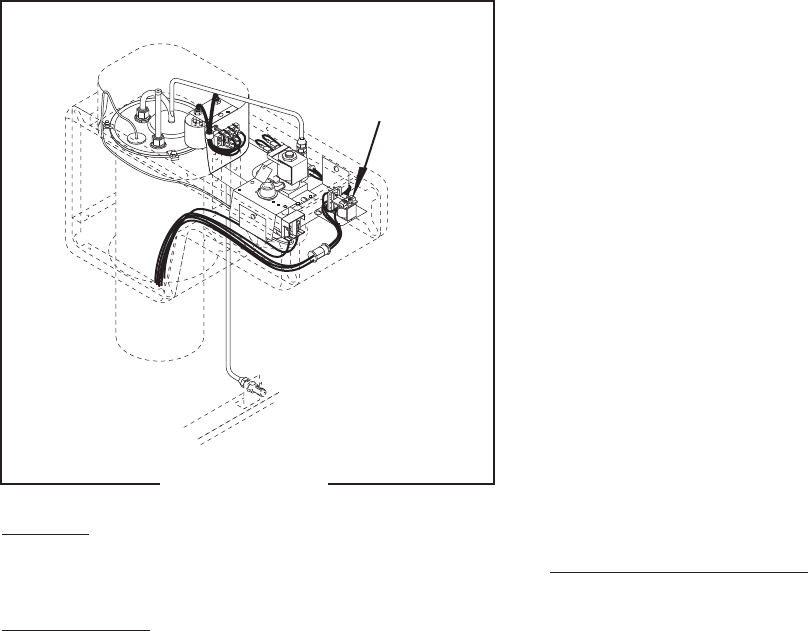
Relay
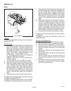
FIG. 22 RELAY
P1478
Location:
The relay is located under the top cover or top warmer
housing, FIG. 22.
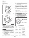
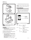
Test Procedure:
1. Disconnect the plug terminal from the relay to the
main wiring harness. Check the voltage across
the pins of the black wire (P3) and white wire
(P2) on the main harness with a voltmeter when
the On/Off brew station warmer switch is in the
upper “ON” position. Connect the brewer to the
power source. The indication must be:
a) 120 volts ac for two wire 120 volt models and
three wire 120/240 volt models,
b) 200 or 240 volts ac for two wire 200 volt or
240 volt models,
c) 100 volts ac for two wire 100 volt models.
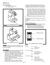
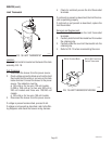
2. Disconnect the brewer from the power source.
3. Check the voltage across the pins of the blue wire
(P1) and white wire (P2) on the main harness
with a voltmeter when the On/Off brew station
warmer switch is in the upper “ON” position and
the start switch is pressed to the lower posi-
tion and held. Connect the brewer to the power
source. The indication must be as described in
step 1.
4. Disconnect the brewer from the power source.
If voltage is present as described, reconnect relay plug
to harness and proceed to #5.
If voltage is not present as described, refer to the Wir-
ing Diagrams and check the brewer wiring harness.
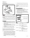
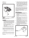
5. Disconnect the plug terminal from the relay to the
solenoid jumper wire. Check the voltage across
the pins of the black wire (P3) and white wire
(P2) on the relay with a voltmeter when the On/
Off brew station warmer switch is in the upper
“ON” position. Connect the brewer to the power
source. The indication must be as described in
step 1.
6. Disconnect the brewer from the power source.
7. Check the voltage across the pins of the blue
wire (P1) and white wire (P2) on the relay with a
voltmeter when the On/Off brew station warmer
switch is in the upper “ON” position and the start
switch is pressed to the lower position and re-
leased. Connect the brewer to the power source.
The indication must be as described in step 1.
8. Disconnect the brewer from the power source.
If voltage is present as described, the relay is operat-
ing properly.
If voltage is not present as described, remove and
replace the relay.
Removal and Replacement:
1. Disconnect the brewer from the power source.
2. Remove the top cover or top warmer housing.
3. Disconnect both plug terminals from the relay.
4. Remove the two #8-32 screws attaching the
relay and bracket assembly to the component
bracket.
5. Remove the #6-32 screw attaching the relay to
the bracket.
6. Securely attach the new relay to the bracket using
the #6-32 screw.
7. Attach the new relay and bracket assembly to
the component bracket using the two #8-32
screws.
8. Reconnect the relay wire terminals to their respec-
tive plugs in the main harness and the jumper
wire at the solenoid valve.
32430 121699