


Page 23
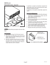
CAUTION :
CAUT
ION
D
IS
C
A
R
D
D
EC
A
N
T
ER
IF
:
.
C
R
A
C
K
E
D
.
S
C
R
A
T
C
H
E
D
.
B
O
I
L
E
D
D
R
Y
.
H
E
A
T
E
D
W
H
E
N
E
M
P
T
Y
.
U
S
E
D
O
N
H
I
G
H
F
L
A
M
E
.
O
R
E
X
P
O
S
E
D
E
L
E
C
T
R
IC
E
L
E
M
E
N
T
S
F
A
ILU
R
E
T
O
C
O
M
P
LY
R
IS
KS
IN
J
U
R
Y
P
N
:
6
5
8
1
9
8
5
B
U
N
N
-O
-
M
A
T
I
C
C
O
R
P
O
R
A
T
I
O
N
F
U
N
N
E
L
CO
N
TE
N
T
S
A
R
E
H
O
T
!
SERVICE (cont.)
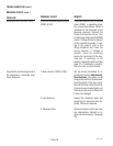
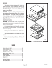
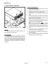
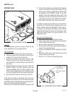
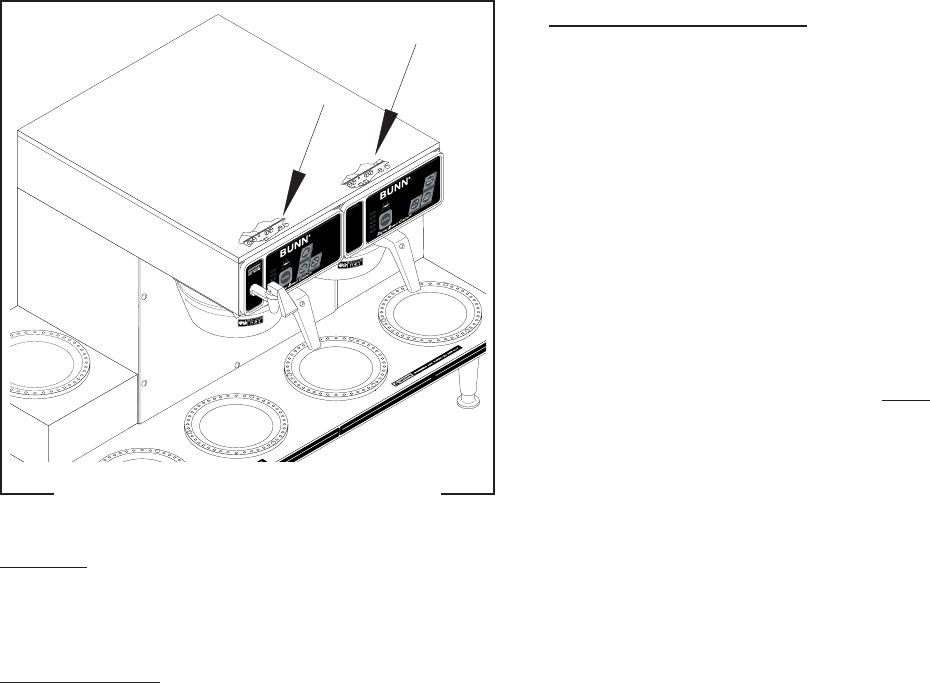
PC CONTROL BOARD - Model CDBC
P1873
FIG. 2 CONTROL BOARDS - CDBC
Location:
The Control Boards are located inside the top
cover behind the front end caps.
Test Procedures:
The test procedures for the control boards will
vary depending upon the problems experienced by the
brewer. Refer to the Troubleshooting guide beginning
on page 10. The troubleshooting guide is divided into
three sections, Refill Circuit, Heating Circuit, and Brew-
ing Circuit.
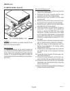
Removal and Replacement:
1. Disconnect the black wire and blue wire from the
relay on the control board.
2. Disconnect the 10-pin connector and the 4-pin
connector from the main wiring harness.
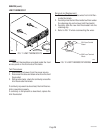
3. Disconnect the 11-pin connector from the control
panel.
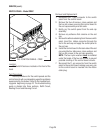
4. Remove the four #6 screws and four nylon wash-
ers and the two #4-40 screws securing the control
board to the end cap assembly.
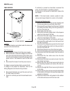
5. Install a new control board and secure with the
four #6 screws and nylon washers and the two #4-
40 screws to the end cap assembly.
NOTE: The four nylon washers must be installed
under the heads of the four #6 screws to prevent
a possible shorting of the control board circuits.
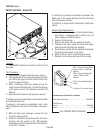
6. Connect the 11-pin connector from the control
panel.
7. Connect the 10-pin connector and the 4-pin con-
nector from the main wiring harness.
8. Connect the blue wire and black wire to the relay on
the control board.
9. Refer to
CDBC Adjustments and Optional Settings
to program the new control board.
29319 091203