


Page 24
C
A
U
T
IO
N
:
C
A
U
T
IO
N
:
C
A
U
T
IO
N
:
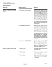
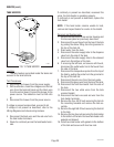
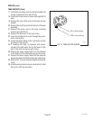
T
R
M
2
J1
J2
J3
J4
J5
J6
J7
T
R
M
1
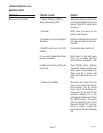
T
R
M
2
J1
J2
J3
J4
J5
J6
J7
T
R
M
1
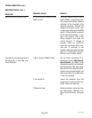
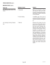
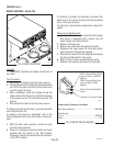
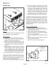
CAUTION :
WARMERS AND SURFACES ARE HOT
O
N
/L
O
W
E
R
STA
R
T
FR
ON
T-SID
E
-R
EA
R
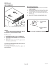
CAUTION :
WARMERS AND SURFACES ARE HOT
O
N/L
O
W
E
R
S
TAR
T
FR
O
N
T
-S
ID
E
-R
EA
R
SERVICE (cont.)
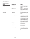
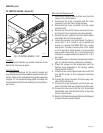
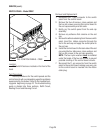
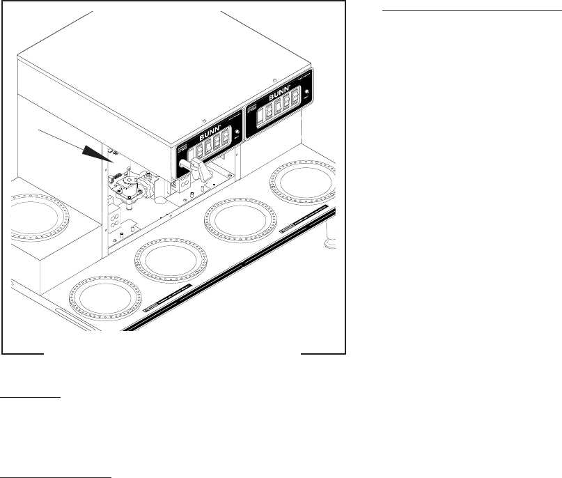
PC CONTROL BOARD - Model CEZ
Location:
The Control Boards are located inside the trunk
behind the front access panel.
Test Procedures:
The test procedures for the control boards will
vary depending upon the problems experienced by the
brewer. Refer to the troubleshooting guide beginning
on page 10. The troubleshooting guide is divided into
three sections, Refill Circuit, Heating Circuit and Brew-
ing Circuit.
P1874
FIG. 3 CONTROL BOARDS - CEZ
Removal and Replacement:
1. Disconnect the black wire and blue wire from the
relay on the control board.
2. Disconnect the 8-pin connector and the 6-pin
connector from the main wiring harness.
3. Disconnect the 2-pin connector from the ready
indicator LED.
4. Remove the four #6-32 screws securing the con-
trol board to the component mounting bracket.
5. Remove the four spacers from the control board
and attach them to the new board.
6. Locate J6 connector on control board. If jumper is
across pins 1 & 2, board is set to operate tea
brewer or a brewer that DOES NOT use a water
level probe. If jumper is across pins 2 & 3, board
is set to operate a coffee brewer or a brewer that
uses a water level probe. Pin 1 of connector J6 is
marked by a square solder pad and pins 2, 3 & 4
are round.
7. Check the jumper on the brew temperature lockout
jack for desired function (enabled or disabled).
8. Check the jumper on the temperature jack for
desired brew temperature. The factory setting
should be 200°F(95°C).
9. Install the new control board and secure with the
four #6-32 screws to the component mounting
bracket.
10. Connect the 2-pin connector from the ready indi-
cator LED to the board.
11. Connect the 8-pin connector and the 6-pin con-
nector from the main wiring harness to the board.
12. Connect the blue wire from the limit thermostat
and the BLK wire from the tank heater to the relay
on the control board.
13. Refer to
CEZ Adjustments and Optional Settings
to
program the new control board.
29319 091203