


Page 26
C
A
U
T
IO
N
:
T
R
M
2
J1
J2
J3
J4
J5
J6
J7
T
R
M
1
T
R
M
2
J1
J2
J3
J4
J5
J6
J7
T
R
M
1
C
A
U
TIO
N
D
IS
C
A
R
D
D
E
C
A
N
T
E
R
IF
:
. C
R
AC
K
E
D
. S
C
R
AT
C
H
E
D
. B
O
ILED
D
R
Y
.
HE
A
T
E
D
W
H
EN
E
M
P
T
Y
. U
SE
D
ON
H
IG
H
F
L
A
M
E
. O
R
EX
P
O
S
ED
E
LE
C
T
R
IC
E
LEM
E
NTS
F
A
IL
U
R
E
T
O
C
O
M
P
L
Y
R
IS
K
S
IN
J
U
R
Y
P
N
:
6
5
8
1
9
8
5
B
U
N
N
-
O
-
M
A
T
I
C
C
O
R
P
O
R
A
T
I
O
N
F
U
N
N
E
L
C
O
N
T
E
N
T
S
A
R
E
H
O
T
!
C
A
UT
IO
N :
WARMERS AND SURFACES ARE HOT
O
N
/LO
W
E
R
S
TA
R
T
FR
O
N
T
-S
ID
E-R
EA
R
C
A
UT
IO
N :
WARMERS AND SURFACES ARE HOT
ON
/LO
W
E
R
S
TA
R
T
F
R
ON
T
-SID
E-R
EA
R
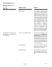
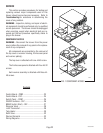
SERVICE (cont.)
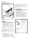
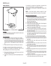
ON/OFF SWITCHES - Model CEZ
Location:
The ON/OFF switches are located on the front of
the hood.
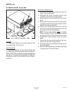
Test Procedure:
1. Disconnect the brewer from the power source.
2. Viewing the switch from the back remove the white
wire from the upper terminal and the black wire
from the center terminal.
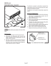
3. With a voltmeter, check the voltage across the
white wire and the black wire. Connect the brewer
to the power source. The indication must be 120
volts ac.
4. Disconnect the brewer from the power source.
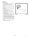
If voltage is present as described, reconnect the white
wire and proceed to #5.
If voltage is not present as described, refer to the
Wiring Diagrams
and check the brewer wiring har-
ness.
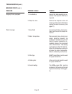
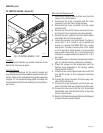
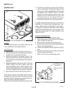
5. With the black wire removed, remove the wire
from the lower terminal.
6. Check for continuity across the center and lower
terminal with the switch in the "ON" position.
Continuity must not be present when the switch is
in the "OFF" position.
P1876
If continuity is present as described, reconnect the
black wire to the center terminal and the remaining
wire to the lower terminal.
If continuity is not present as described, replace the
switch.
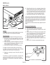
Removal and Replacement:
1. If switch to be removed is in the left control panel
and brewer is equipped with a faucet, turn off
water supply and remove faucet.
2. Remove front end cap
3. Remove the wires from the switch terminals.
4. Compress the clips inside the hood and gently
push the switch through the opening.
5. Push the new switch into the opening and spread
the clips to hold switch in the hood.
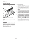
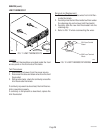
6. Refer to FIG. 6 when reconnecting the wires.
7. Replace front end cap and faucet (if removed).
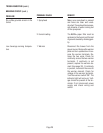
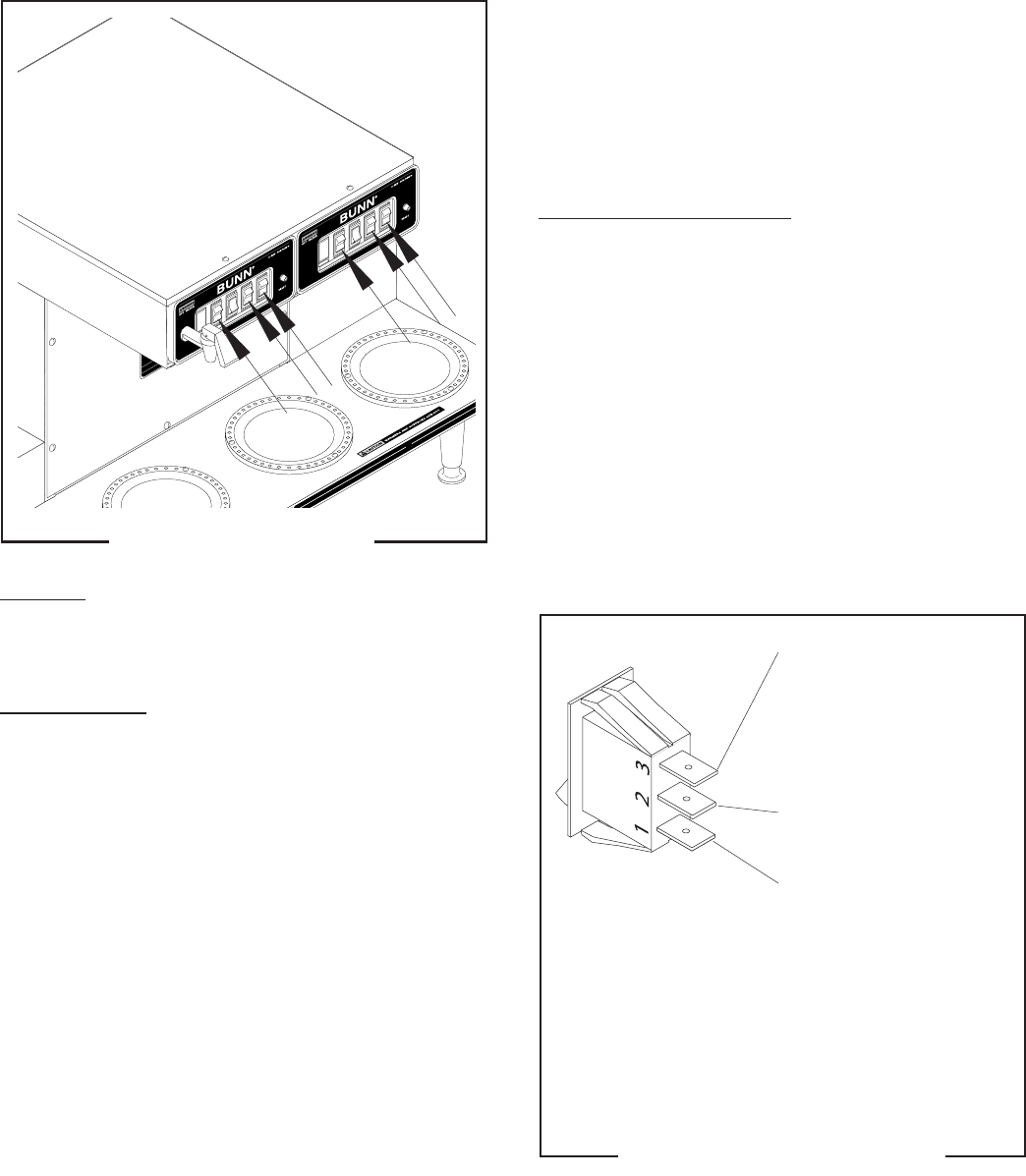
FIG. 5 ON/OFF SWITCHES
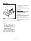
Connect wire to Terminal #1 as follows:
Brew Station Warmers............................................ WHI/RED
Side Warmers
(Front) .................................................................... BRN/BLK
(Rear) .............................................................................. VIO
P1918
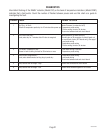
WHI to Terminal Block (White
Insert on 120V or 120/240V
Models)
RED to Terminal Block (Red
Insert on 200V or 230V
Models)
BLK to Terminal Block (Black
Insert)
Terminal #1 (See chart below)
FIG. 6 ON/OFF SWITCH WIRING
29319 091203