


Page 17
SERVICE (cont.)
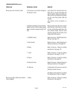
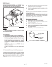
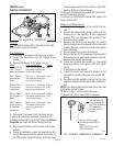
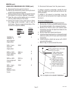
CONTROL THERMOSTAT
FIG. 6 CONTROL THERMOSTAT
P2209.60
Location:
The control thermostat is mounted on the right
front of the component bracket.
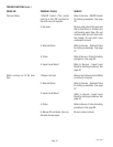
Test Procedures:
1. Disconnect the brewer from the power source.
2. Locate the thermostat and the voltage check
points.
3. Connect the brewer to the power source.
Model
120/208V & 120
240V - 3 wire w/
ground single phase
230V - 2 wire w/
ground single
phase
208V or 240V - 2
wire w/ground
single phase
280V or 440V - 4
wire w/ground 3
phase
380V - 3 wire w/
ground 3 phase
w/ stepdown
transformer
4. Disconnect the brewer from the power source.
If voltage is present as described, proceed to #5.
If voltage is not present as described, refer to the Wiring
Diagrams and check the brewer wiring harness.
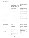
5. Disconnect the black wires from the control ther-
mostat.
6. Check for continuity across the terminals on the
control thermostat with the control thermostat in
the "ON" position (fully clockwise), continuity must
Check Voltage Across
Black wire on thermostat
from main harness to white
wire in terminal block.
Red wire on thermostat
from main harness to black
wire in terminal block.
Black wire on thermostat
from main harness to red
wire in the terminal block.
Black wire on thermostat
from main harness to white
wire in terminal block.
Black wire on thermostat
from main harness to white
wire on step down trans-
former.
Voltage
120V
230V
208V or
240V
220V or
254V
120V
not be present when the thermostat is in the "OFF"
position (fully counterclockwise).
If continuity is present as described, the control ther-
mostat is operating properly.
If continuity is not present as described, replace the
control thermostat.
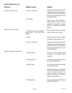
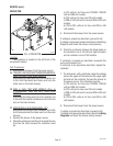
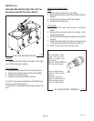
Removal and Replacement:
1. Disconnect the wires from the control thermo-
stat.
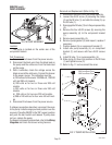
2. Remove the thermostat capillary bulb by firmly
pulling up on the capillary at the component
bracket. This will disengage the grommet from
the component bracket.
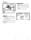
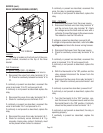
3. Remove the #8-32 screw securing the control
thermostat and mounting bracket to the component
bracket. Remove control thermostat and bracket
as an assembly.
4. Remove knob from control thermostat.
5. Remove the two #6-32 screws securing the control
thermostat to the thermostat mounting bracket.
Remove and discard thermostat.
6. Install new control thermostat on thermostat
mounting bracket and secure with two #6-32
screw.
7. Install knob on thermostat.
8. Install thermostat and mounting bracket on the
component bracket and secure with one #8-32
screw.
9. Carefully bend the capillary tube so that the tube
and bulb inside the brewer are in the vertical posi-
tion.
NOTE: The capillary tube must be clear of any electrical
termination and not kinked.
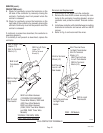
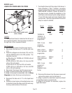
10. Refer to Fig. 7 and reconnect the wires.
11. Adjust the control thermostat as required.
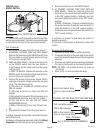
BLK from Main Har-
ness (All Models Ex-
cept 230V CE Models
RED from Main
Harness (230V CE
Models)
BLK to Limit Thermostat
(All Models Except 230V CE
Models
RED to Limit Thermostat
(230V CE Models)
P1730.80
FIG. 7 CONTROL THERMOSTAT TERMINALS
10060 080900