


Page 27
SERVICE (cont.)
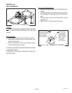
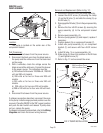
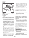
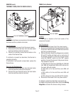
SOLENOID
FIG. 22 SOLENOID
P2209.60
Location:
The solenoid is mounted on the upper left rear of
the component bracket.
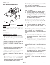
Test Procedures:
1. Disconnect the dispenser from the power
source.
2. A) For 120/208 volt and 120/240 volt three wire,
single phase models, 380 volt three wire, three
phase models and 380 volt, 440 volt four wire,
three phase models, disconnect the black wire
from the liquid level board #2 and the white wire
on the solenoid. With a voltmeter, check the voltage
across the black and the white wire. Connect the
brewer to the power source. The indication must
be:
a) 120 volts ac for 380 volt three wire, three phase
models and 208 0r 240 volts ac for four wire three
phase 440 volt models.
b) 208 volts ac for three wire 120/208 volt mod-
els.
c) 240 volts ac for three wire 120/240 volt mod-
els.
B) For 208 volt, 240 volt two wire single phase and
208 volt, 240 volt three wire three phase models,
disconnect the black wire from the liquid level
board #2 and the red wire from the solenoid. With
a voltmeter, check the voltage across the black and
red wires. Connect the brewer to the power source.
The indication must be:
a) 208 volts ac for 208 volt two wire single phase
and 208 volt three wire three phase models.
b) 240 volts ac for 240 volt two wire single phase
and 240 volt three wire three phase models.
C) For 230V - CE two wire single phase models,
disconnect the red wire from the liquid level board
#2 and the black wire from the solenoid. With a
voltmeter, check the voltage across the red wire and
the black wire. Connect the brewer to the power
source. The indication must be 230 volts ac.
3. Disconnect the dispenser from the power
source.
If voltage is present as described, proceed to #4.
If voltage is not present as described, refer to the brewer
Wiring Diagrams and check the wiring harness.
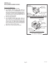
4. Disconnect the blue wire and the white wire, the
blue wire and the red wire or blue wire and black
wire from the solenoid terminals.
5. Check for continuity across the solenoid valve coil
terminals.
If continuity is present as described, reconnect the
wires to the solenoid.
If continuity is not present as described, replace the
solenoid valve.
6. Check the solenoid valve for coil action. Connect
the dispenser to the power source. Listen carefully
in the vicinity of the solenoid valve for a "clicking"
sound as the coil magnet attracts.
If the sound is heard as described and water will not
pass through the solenoid valve, there may be a block-
age in the water line before the solenoid valve or, the
solenoid valve may require inspection for wear, and
removal of waterborne particles.
If the sound is not heard as described, replace the
solenoid valve.
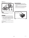
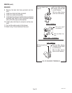
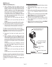
Removal and Replacement:
1. Remove the wires from the solenoid valve.
2. Turn off the water supply to the dispenser.
3. Disconnect the water inlet line from the connector
on the solenoid valve.
4. Remove the #10-32 screw and the flat washer
securing the liquid level board, shield and the
solenoid to the component bracket.
5. Remove solenoid, connectors, air chamber and
tank inlet tube as an assembly.
10060 080900