


Page 30
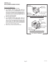
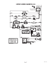
BLK to Contactor T1 (All
Models Except 230V-CE
Models)
BLK (Thermal Fuse) to
Contactor Top Left Termi-
nal) (230V-CE Models)
RED to Contactor T2 (All
Models Except 230V-CE
Models)
RED (Thermal Fuse) to Con-
tactor Top Right Terminal)
(230V-CE Models)
BLK to Contactor L1
(120/208V, 120/240 Three
Wire Single Phase, 208V
and 240V Two Wire,
Single Phase)
BLU to Main Harness
(208V, 240V, 380V Three
Wire ,Three Phase and
380V,440V Four Wire,
Three Phase
BLK (Thermal Fuse to
Contactor Lower Left
Terminal) (230V-CE Mod-
els)
RED to Contactor L2
(120/208V, 120/240 Three
Wire Single Phase, 208V
and 240V Two Wire, Single
Phase)
BLU to Main Harness
(208V, 240V, 380V Three
Wire ,Three Phase and
380V,440V Four Wire,
Three Phase
RED (Thermal Fuse) to
Contactor Lower Right
Terminal)
SERVICE (cont.)
TANK HEATERS
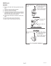
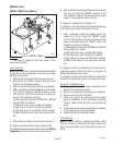
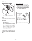
FIG. 27 TANK HEATER TERMINALS
P1746
LEFT
RIGHT
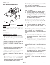
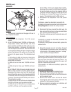
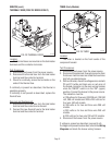
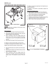
FIG. 26 TANK HEATER
P2209.60
Location:
The tank heaters are located on the right center
and the left center of the component bracket.
Test Procedures:
1. Disconnect the brewer from the power source.
2. Disconnect the wires from the tank heater.
3. Check for continuity across the tank heater termi-
nals.
If continuity is present as described, proceed to #4.
If continuity is not present as described, replace the
tank heater.
Removal and Replacement:
1. Remove the wires or thermal fuses from the tank
heater.
2. Remove the four #8-32 screws securing the tank
heater to the component bracket.
3. Remove tank heater and gasket.
4. Position new tank heater and gasket on the compo-
nent bracket and secure with four #8-32 screws.
5. Refer to Fig. 27 and reconnect the wires.
10060 031599