


Page 14
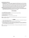
BREW TIMER (early models)
SERVICE (cont.)
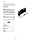
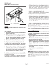
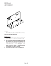
Location:
The brew timer is located in the hood, to the right
of the tank.
Test Procedure:
1. Disconnect the brewer from the power source and
separate the polarized, three-pin connectors be-
tween the timer and brewer wiring harness and
rotate the brew timer dial fully counterclockwise.
2. With a voltmeter, check the voltage across sock-
ets 2 & 3 (white and black wires) of the female
connector when the On/Left switch is in the upper
position. Connect the brewer to the power source.
The indication must be 120 volts ac.
3. Disconnect the brewer from the power source.
If voltage is present as described, proceed to #4. If
voltage is not present as described, refer to the
Wir-
ing Diagram
and check the brewing harness.
4. With a voltmeter, check the voltage across sock-
ets 1 & 2 (blue and white wires) of the female
connector when the On/Left switch is in the upper
position and the Start switch is pressed to the
lower position and held. Connect the brewer to
the power source. The indication must be 120 volts
ac until the Start switch is released.
5. Disconnect the brewer from the power source.
If voltage is present as described, reconnect the po-
larized, three-pin connectors, and proceed to #6. If
voltage is not present as described, refer to the
Wir-
ing Diagram
and check the brewer wiring harness.
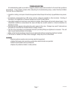
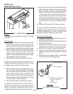
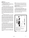
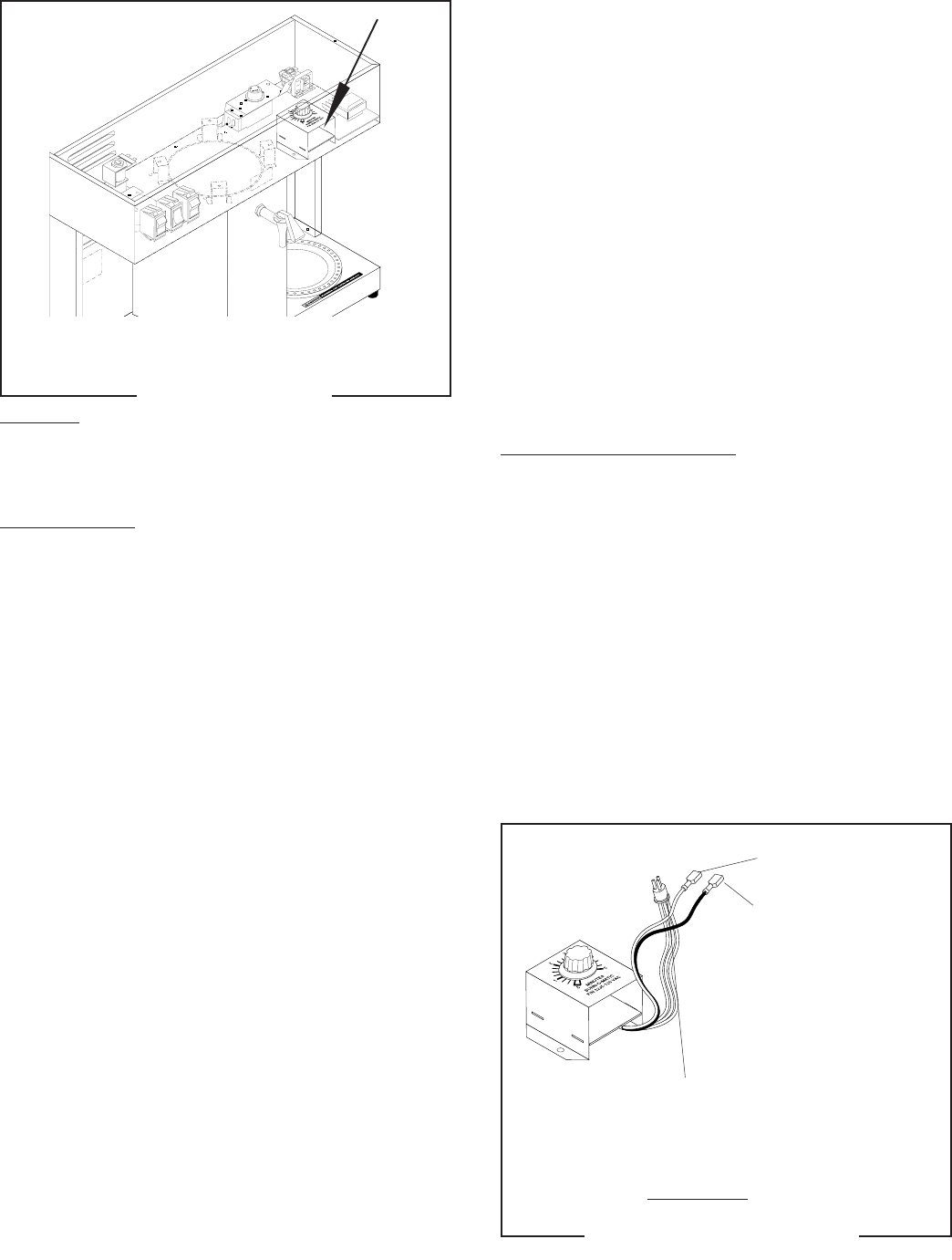
5
WHI to Relay Coil
BLK to Relay Coil
P1 BLU/BLK to Start Switch
P2 WHI to Liquid Level
Board
P3 BLK to Relay
P1980
FIG. 3 BREW TIMER WIRING
OLD STYLE
6. Disconnect the in-line connectors on the black and
white wires from the timer to the wiring harness.
7. With a voltmeter, check the voltage across the
black and white wires when the On/Left switch is
in the upper position and the Start switch is
pressed to the lower position and released. Con-
nect the brewer to the power source. The indica-
tion must be 120 volts ac for approximately 20
seconds and then return to its previous indica-
tion.
8. Disconnect the brewer from the power source.
If voltage is present as described, the brew timer is
operating properly. Reset the timer dial as required,
to obtain the desired brew volume. If voltage is not
present as described, replace the brew timer.
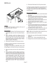
Removal and Replacement:
1. Separate all connectors between the brewer wir-
ing harness and the timer.
2. Remove the two #8-32 nuts holding the timer to
the inside of the hood.
3. Install the new timer circuit board as described in
Late Model Timer section on the following pages.
4. Refer to FIG. 5 when reconnecting the wires.
5. Install the Timer Setting decal provided with the
replacement timer kit, on the bottom of the top
cover.
6. Adjust the timer as required. Refer to Late Model
Timer section on the following pages.
P1979.75
FIG. 2 BREW TIMER
10179 060100