


Page 15
BREW TIMER (cont.)(late models)
10179 060100
P2172.80
SERVICE (cont.)
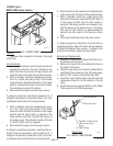
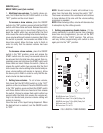
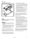
Location:
The brew timer is located in the hood, to the right
of the tank.
Test Procedures:
1. Disconnect the brewer from the power source and
remove the top cover.
2. With a voltmeter, check the voltage across termi-
nals TL1 and TL2 when the “ON/OFF” switch is in
the “ON” position. Connect the brewer to the power
source. The indication must be 120 volts ac.
3. Disconnect the brewer from the power source.
If voltage is present as described, proceed to #4.
If voltage is not present as described, refer to the
Wiring Diagram
and check the brewer wiring harness.
4. Disconnect the white/blue wire from terminal TL3
and the blue/black wire from terminal TL5. Check
for continuity across the two wires when the start
switch is pressed to the “START” position.
If continuity is present as described, reconnect the
wires and proceed to #5.
If continuity is not present as described, refer to the
Wiring Diagram
and check the brewer wiring harness.
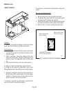
FIG. 4 BREW TIMER
5. With a voltmeter, check the voltage across termi-
nals TL1 and TL4 when the “ON/OFF” switch is in
theh “ON” position. Connect the brewer to the
power source. The indication must be 0 volts.
If voltage is as described, proceed to #6.
If voltage is not as described, disconnect the brewer
from the power source and replace the timer.
6. With a voltmeter, check the voltage across termi-
nals TL1 and TL4 when the “ON/OFF” switch is in
the “ON” position. Connect the brewer to the power
source and press the start switch. The indication
must be 120 volts ac.
If voltage is present as described, the brew timer is
operating properly. Reset the timer as required, to
obtain the desired brew volume.
If voltage is not present as described, disconnect the
brewer from the power source and replace the timer.
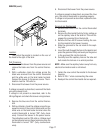
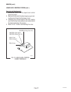
Removal and Replacement:
NOTE: Do not remove or install wires while timer board
is installed. Pressure applied to one side may cause
damage to the board.
1. Remove the two #8-32 nuts securing circuit board
to the hood.
2. Remove circuit board and spacers (as required).
3. Remove all wires from the timer.
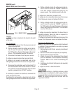
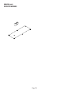
4. Attach all wires to the replacement timer board
prior to installation to the component mounting
bracket. Refer to FIG. 5 when reconnecting the
wires.
5. Install new circuit board with spacers (as required)
to the hood.
6. Adjust the timer as described below.
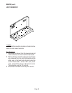
Timer Setting:
NOTE: Prior to setting or modifying volumes, check
that the brewer is connected to water supply, the tank
is properly filled, and a funnel and server are in place.
NOTE: All volume settings must be done with the
sprayhead installed.