


Page 17
SERVICE (cont.)
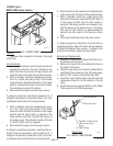
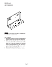
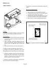
Location:
The control thermostat is located on the rear of
the hood to the right of the tank.
Test Procedure:
1. Disconnect the brewer from the power source and
remove the black wire from the control thermo-
stat.
2. With a voltmeter, check the voltage across the
black wire removed from the control thermostat
and the white wire on the tank heater terminal.
Connect the brewer to the power source. The in-
dication must be 120 volts ac.
3. Disconnect the brewer from the power source.
If voltage is present as described, reconnect the black
wire and proceed to #4.
If voltage is not present as described, refer to the
Wiring Diagram
and check the brewer wiring harness.
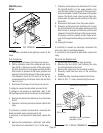
4. Remove the blue wire from the control thermo-
stat.
5. With a voltmeter, check the voltage across the ex-
posed terminal of the control thermostat and the
white wire on the tank heater terminal when the
control thermostat is turned “ON” (fully clock-
wise). Connect the brewer to the power source.
The indication must be 120 volts ac. Voltage must
not be indicated across these terminals when the
thermostat is turned “OFF” (fully counterclock-
wise).
6. Disconnect the brewer from the power source.
If voltage is present as described, reconnect the blue
wire, the control thermostat is operating properly.
If voltage is not present as described, replace the con-
trol thermostat.
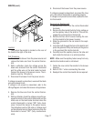
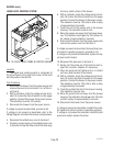
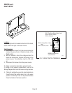
Removal and Replacement
1. Remove both wires from the control thermostat
terminals.
2. Remove the thermostat bulb by firmly pulling up
on the capillary tube at the tank lid. This will dis-
engage the grommet from the tank lid.
3. Remove the two #8-32 screws holding the con-
trol thermostat to the brewer housing.
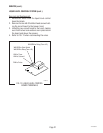
4. Slide the grommet to the red mark on the capil-
lary tube.
5. Insert the bulb through the hole in the tank lid and
press the grommet firmly and evenly so the groove
in the grommet fits into the tank lid.
6. Carefully bend the capillary tube so the tube and
bulb inside the tank are in a vertical position.
NOTE - Make sure the capillary tube is away from any
electrical termination and is not kinked.
7. Fasten the new control thermostat to the brewer
housing.
8. Refer to FIG. 7 when reconnecting the wires.
9. Readjust the control thermostat dial as required.