


Page 20
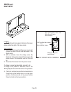
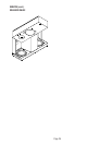
LIQUID LEVEL CONTROL SYSTEM
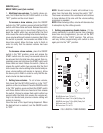
Location:
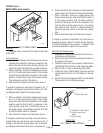
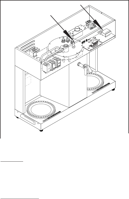
The liquid level control system is composed of
the circuit board in the right front corner of the hood
and the probe in the tank lid.
Test Procedure:
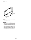
1. Disconnect the brewer from the power source and
remove the wires from terminals 1 & 4 of the cir-
cuit board.
2. With a voltmeter, check the voltage across termi-
nals 2 & 3 when the On/Left switch is in the upper
position. Connect the brewer to the power source.
The indication must be 120 volts ac.
3. Disconnect the brewer from the power source.
If voltage is present as described, proceed to #4.
If voltage is not present as described, refer to the
Wiring Diagram
and check the brewer wiring harness.
4. Reconnect the white/brown wire to terminal 1.
5. Carefully connect a piece of insulated jumper wire
to terminal 4. Keep the other end of this wire away
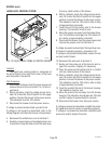
FIG. 12 LIQUID LEVEL PROBE & CONTROL BOARD
P
N
:
6
5
8
B
U
N
N
O
F
F
H
I
P2173.80
10179 060100
SERVICE (cont.)
from any metal surface of the brewer.
6. With a voltmeter, check the voltage across termi-
nals 1 & 3 when the On/Left switch is in the upper
position. Connect the brewer to the power source.
The indication must be 120 volts ac after a delay
of approximately 5 seconds.
7. Touch the end of the jumper wire to the brewer
housing. The indication must be zero.
8. Move the jumper wire away from the brewer hous-
ing. The indication must again be 120 volts ac af-
ter a delay of approximately 5 seconds.
9. Disconnect the brewer from the power source and
remove the jumper wire from terminal 4.
If voltage is present as described, the liquid level con-
trol board is operating properly, proceed to #10.
If voltage is not present as described, replace the liq-
uid level control board.
10. Reconnect the pink wire to terminal 4.
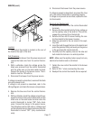
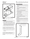
11. Gently pull the probe out of the tank lid and in-
spect for corrosion. Replace it if necessary.
12. Place the probe so that neither end is in contact
with any metal surface of the brewer.
13. With a voltmeter, check the voltage across termi-
nals 1 & 3 when the On/Left switch is in the upper
position. Connect the brewer to the power source.
The indication must be 120 volts ac after a delay
of approximately 5 seconds.
14. Touch the probe’s flat end to the brewer housing.
The indication must be zero.
15. Move the probe’s flat end away from the brewer
housing. The indication should again be 120 volts
ac after a delay of approximately 5 seconds.
16. Disconnect the brewer from the power source.
If voltage is present as described, reinstall the probe,
the liquid level control system is operating properly.
If voltage is not present as described, check the pink
probe wire and/or replace the probe.